EXTRUSION
PROCESSES
Metal Extrusion
Impact Extrusion
Hydrostatic Extrusion
MANUFACTURING
PROCESSES
Metal Casting
Metal Forming
Metal Rolling
Metal Forging
Metal Drawing
Sheet Metal
Powder Processes
Metal Extrusion Design
Design of a metal extrusion manufacturing process involves consideration of many different factors. The primary goal is to create a process that enacts a smooth and effective flow of material. In general, force necessary is minimized as much as possible. Higher forces require greater capacity and energy. Higher forces also increase the chances of part defects, die wear and die breakage. Friction has an important roll when extruding a part and should be maintained at an optimum level. By examining and understanding the causes of metal extrusion defects, the process engineer can design a particular operation to mitigate the chances of defects occurring. Defects fall into different categories and have several root causes. Most defects are similar, less specifically, in that they are created by improper material movement and stress distributions. Control of operational factors will allow for control of forces and metal flow, producing efficient, defect free metal extrusions. In addition to operational factors, the geometric profile of the extrusion also affects the manufacture of the part.
Troubleshooting Defects
Extrusion defects that occur during the manufacturing process generally fall into three basic categories. Internal breakage, particularly in the center, surface cracking, and piping.
Center Cracking
Internal breakage; common names used in manufacturing industry for this type of defect are center cracking, cheveron cracking, arrowhead fracture, and centerburst. As the work piece is being extruded through the die, stresses within the work break the material causing cracks to form along the central axis of the extruded section. Center cracking is a difficult defect to detect since it occurs within the material of the part. Figure 219 shows a metal extrusion subject to centerburst, the part has been cut in a half section so that the defect may be observed.
Figure:219 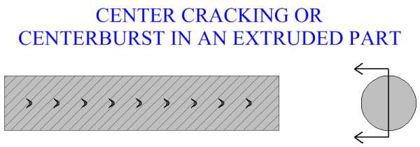
|
To understand the causes of center cracking, it is important to understand the flow of the metal that is occurring while extruding a profile. As mentioned in the material flow section, the outer region of the metal extrusion will experience more deformation, more material displacement and more turbulent flow than the areas towards the central region. The difference between the metal movement of the outer regions compared to that of the central region is critical. If the material displacement occurring in the outer areas is of a much greater magnitude than that which is occurring in the central area, then the difference will cause high stresses to develop within the material. The greater the difference in metal flow characteristics between regions, the greater the stresses that will occur. If the stress level becomes too high, then material breakage will occur in the form of internal cracks.
In manufacturing practice, selection of die angle will be a primary factor in preventing center cracking. High die angles will favor center cracking in a metal extrusion more than low die angles will. The reason being the greater flow turbulence created in the outer regions of the work. Higher fiction, in general, will tend to reduce the chances of center cracking. Cracks will propagate over inclusions, therefore the greater the amount of inclusions in the work material, the more favorable the conditions for the occurrence of this metal extrusion defect. High extrusion ratios are less likely to promote center cracks than lower ones.
Surface Breakage
Surface breakage defect on a metal extrusion, is breakage on the surface of the part. Most surface defects are in the form of cracks that extend from the surface into the parts material, to varying degrees. These cracks usually occur along the grain boundaries of the metal. The primary cause of surface cracking defect in metal extrusion manufacture is excessive stresses on the surface of the part's material. Friction is a large factor in controlling surface breakage, while manufacturing an extruded section. Increased friction will create a more favorable environment for surface cracking. Lubrication can help reduce friction, so can an increased die angle.
When designing a metal extrusion manufacturing process, it is important to balance all factors such as friction. Lower friction may create better conditions at the surfaces between the work and die. However, if friction forces are too low, a more turbulent outer flow may result in center cracking. Another important factor in surface breakage defect is the hardness of the work stock material. The speed at which the part is extruded is also a consideration. Higher extrusion speeds will create conditions more favorable to material breakage.
Conditions in which the work material sticks to the extrusion die can be a cause of surface cracking. Work sticking to tool surfaces can sometimes be a problem in many different kinds of manufacturing operations, especially with some specific materials. It is a common case that when the extrusion sticks to the die, pressure builds up behind the material. Enough force breaks loose the work, causing cracks in the metal. The part shoots forward a small distance, then it sticks to the die again. This cycle repeats itself as the part is being extruded. The cracks will appear at spaced intervals around the part's peripheral. This is somewhat reminiscent of the appearance of a bamboo tree, thus this particular manufacturing defect is termed bamboo defect.
Surface cracking of a metal extrusion need not have a mechanical cause, often the root cause of cracking of a metal being extruded will be thermal stresses. High thermal gradients between the work and die interface can cause the extrusion's surfaces to loose heat rapidly. Heated die and lubrication can help mitigate thermal gradients at surfaces. The work billet should be heated to the best temperature considering the operational variables. Extrusion speed and friction are critical factors in controlling the thermal characteristics of this type of metal manufacturing process. Higher extrusion speeds can not only generate greater mechanical forces, but more heat as well. Increases in heat generation during the process can crack the work material.
Piping Defect
Piping, also called tailpipe or fishtailing, is a defect common when manufacturing sections by direct extrusion. The use of a dummy block and good surface preparation of the work can help avoid piping. Piping occurs in the work material at the end opposite to the die. Piping is a result of improper metal flow during the extrusion operation. Piping manifests itself as a funnel shaped void of material at the end of the work. As mentioned before, metal flow is a very important consideration in any forming operation. The way to solve a piping problem is to enact a smooth metal flow during the extrusion process. The combination of friction and thermal gradients acting at the die-work interface needs to be observed, and their cumulative effect on the metal flow occurring during the process determined. The manufacturing engineer must control the different process variables to achieve the smoothest material flow possible during the metal extrusion operation.
Figure:220 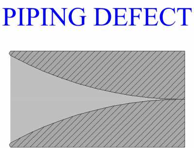
|
Metal Extrusion Design For Manufacture
When designing a metal extrusion process, the geometric profile of the extruded section is an important factor affecting the forces involved, metal flow, die wear and part quality. Some cross sections, when extruded, will produce undesirable force distributions and metal flow. If possible, it is desirable to design for manufacture. This section will discuss the effect of different features of a profile and how to optimize the cross section for metal extrusion manufacture.
First, it is important to understand that the nature of the forces involved in metal extrusion are fundamentally different than those of other forming processes. For example, in a process such as metal forging, the forces acting on the operation will vary throughout the process, stress will change as the forging stroke progresses. With extrusion, (although in direct extrusion there is somewhat of a decrease in the necessary force, as the operation progresses, due to decreasing friction with billet length), the forces acting are generally consistent throughout the bulk of the operation.
Some components need to have a very specific geometry and must be manufactured that way. However, if manufactured products may be geometrically altered in such a way as to ease in their manufacture, without changing their ability to perform their desired function, then they should be redesigned for manufacture. Symmetry is generally preferred in extruded metal cross sections, particularly with regard to open areas of the cross section. Open areas in an extrusion's cross section will complicate the process by changing the forces involved. Die wear and breakage are primary considerations of a manufacturing process designer when designing a metal extrusion operation. Controlling material flow is essential in metal forming manufacture. In addition, the stresses applied to the die, as a result of this metal flow, must be calculated and the mold must be designed to handle these forces. Some areas of the die may be subject to greater stresses than others. Some areas of a die may not be able to handle as much stress as others. The geometry of the mold must be considered carefully with respect to the forces created, as the part is being extruded.
Excessive stresses in places that can not handle it, can cause rapid wear and die breakage. Extrusion die tongues cause a weaker area in the die's geometry. The location of die tongues and the forces they are subject to are an important factor in die design.
Figure:221 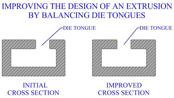
|
Symmetry provides for more balanced forces and helps avoid overstressing areas of the extruding die. Hollow areas within the cross section, in particular, should be balanced.
Figure:222 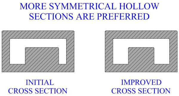
|
Usually, larger hollow areas cause more difficulties during the metal extrusion operation. Reducing the area of hollow sections, if possible, may ease the manufacturing operation. If hollow sections can be eliminated completely, in favor of a single solid extrusion, it would be a better design for manufacture.
Figure:223 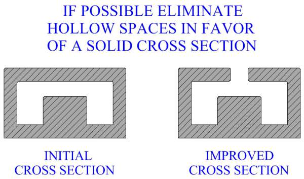
|
Thin walled metal extrusions are often produced in manufacturing industry, however, there are limits to the minimum wall thickness. Minimum wall thickness of an extrusion depends largely on the type of extruded metal. Minimum wall thickness for aluminum extrusions is usually about .040 inches. A common type of extruded steel may have a minimum wall thickness of three times that of aluminum. Standard wall thickness throughout the profile is desirable, if not, the wall thickness should be as balanced as possible.
Figure:224 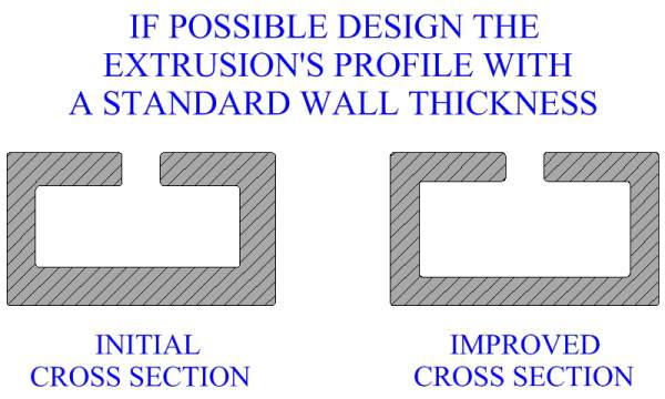
|
One way to improve the design of a metal extrusion process that requires a cross section of walls of different thickness, is to smooth the transition between thick to thin walls with a large radius.
Figure:225 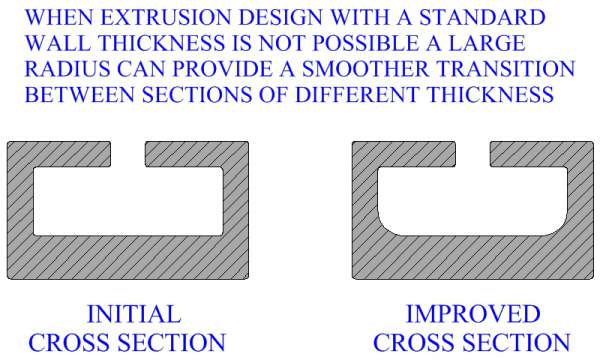
|
The manufacturing designer should avoid sharp corners in a metal extrusion's profile, if at all possible.
Figure:226 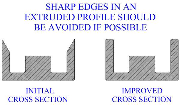
|
As mentioned earlier, die tongues are critical areas for mold wear and breakage. Rounding certain corners of a metal extrusion can strengthen die tongues.
Figure:227 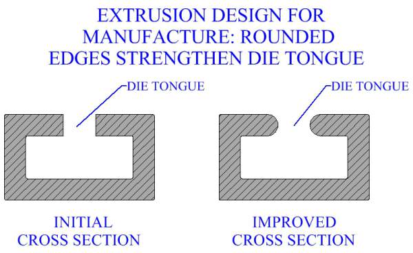
|