MANUFACTURING PROCESSES Metal Casting Metal Forming Metal Rolling Metal Forging Metal Extrusion Sheet Metal Powder Processes
Metal Drawing
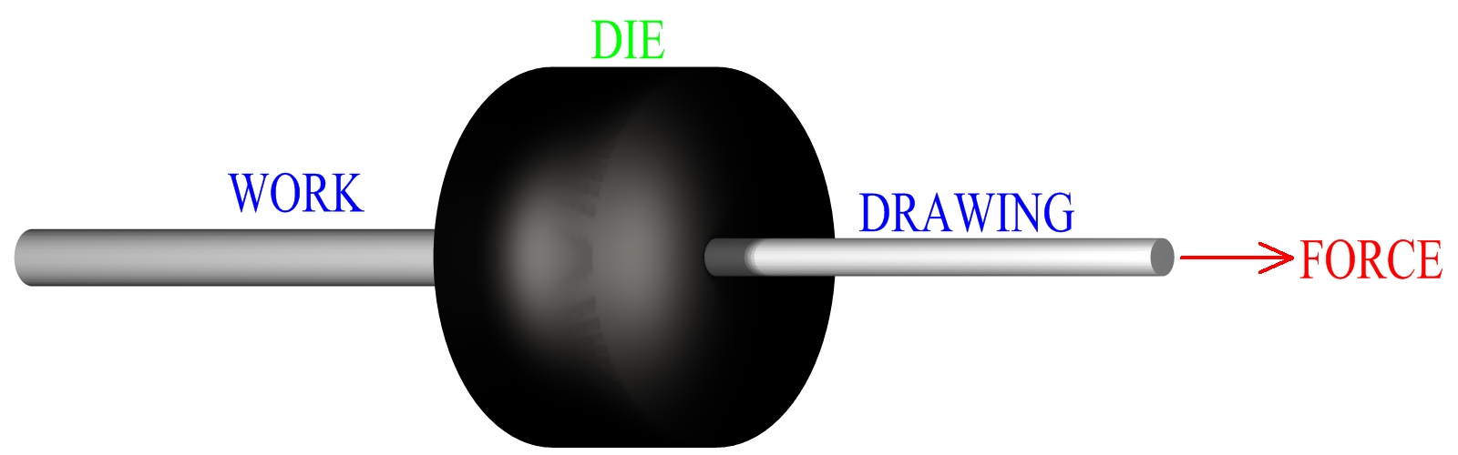
Metal drawing is a manufacturing process that forms metal work stock by reducing its cross section. This is accomplished by forcing the work through a mold, (die), of smaller cross sectional area than the work. This process is very similar to metal extrusion, the difference being in the application of force. In extrusion the work is pushed through the die opening, where in drawing it is pulled through. The basic concept of metal drawing is illustrated in the following figure.
Figure:236
|
Many of the same manufacturing factors of metal extrusion are also present in metal drawing. Similar to extrusion, the die angle, amount of area reduction and geometry of cross sections are all essential considerations. Friction and its effects on metal flow should be controlled. There is a fundamental difference between metal extrusion and metal drawing practice, based on the fundamental difference between the two processes. Metal extrusion can provide tremendous reductions in cross sectional area by pushing the material through the mold. In metal drawing the amount of cross sectional reduction is much more limited, by the fact that the metal is pulled through. As in extrusion, the greater the reduction in cross sectional area the greater the force required to form the work. When the force needed to pull a work piece through a mold exceeds the yield strength of the work, it will begin to yield. Yielding of the work in this manner is not desirable in metal drawing manufacture.
In theory the highest possible amount of area reduction, based on preventing yielding of the work, is usually about 63%. In industrial manufacturing practice, area reductions generally range from 15% to 45%. In order to obtain greater reductions in cross sectional area, the work may be drawn through two or more drawing die in series. Metal drawing often involves round profiles. The term draft is used to denote the reduction in diameter of drawn round cross sections. In addition to the specific cross sectional reduction, the work material and the speed at which the product is drawn are also critical operational factors when manufacturing by metal drawing.
Metal Drawing Process
The metal drawing process in manufacturing industry is usually performed cold. Cold working will impart the drawn product with accurate tolerances, favorable grain structure, improved material properties and good surface finish. Preparation of the work, prior to drawing, is an important part of the operation. The work is sometimes annealed first, to recover the material from existing stresses. Next the work surfaces are cleaned. Common industrial practice for cleaning metal stock includes shot blasting or submersion in some, (typically acidic), solution. The work is then washed to remove any solution, it may also be dried at a low temperature. After the cleaning phase the stock may be conditioned, this can involve the application of a variety of different chemical solutions to the surface of the work. Specific chemicals used depend on the manufacturing situation and the work material. The main reason for these conditioning agents is to help the work surface hold the lubrication necessary for the process.
Once prepared, the work piece is pointed at one end, allowing that end to be inserted through the die. This end is then mechanically gripped so that the rest of the work can be pulled through. At certain points in the process, the drawn product may require straightening. Straightening rolls can be employed as part of the manufacturing process. Metal drawing can be either a discrete or continuous operation and can be very economically efficient for certain applications. In commercial industry, this process provides stock material for machining operations and for the manufacture of such items as fences, coat hangers, nails, screws and bolts. Metal wire drawing plays a huge roll in the manufacturing industry in the production of cable and electrical wire.
Drawing Dies
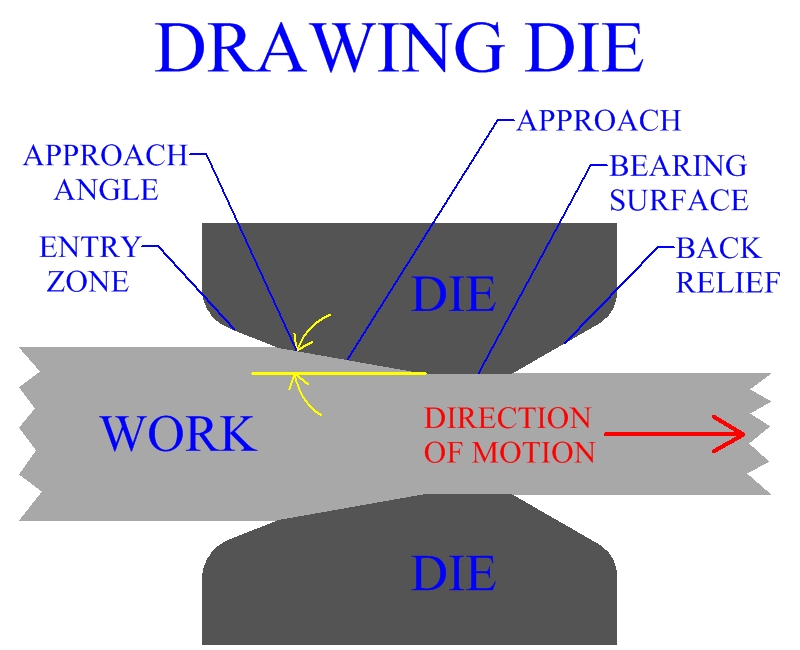
Metal drawing dies, in manufacturing industry, are usually made of cemented carbides or tool steels. Mandrels for tube drawing are often made of similar materials as the die. Occasionally diamond die are employed to form extremely thin wire. As the work transverses the mold it passes through different sections. The die's first section is a bell curved opening. This area does not contact the work, but helps filter lubricant into the mold and allows for adequate entry of the work into the mold without damage from die edges. Next, the forming of the work occurs in the approach section. The approach angles down the cross sectional area, connecting with the next section, the bearing surface. Bearing surface, also known as land, holds the precise geometric cross section for a length of the draw. This acts as a sizing operation, ensuring tight tolerances. The last section is the exit zone, this is a steeply angled section similar to the entry zone. Exit zones are used to protect drawn work from the edges of the die.
Figure:237
|
Defects In Metal Drawing
Defects that occur in metal drawing manufacture are similar to those that occur while manufacturing by extrusion. Controlling metal flow is essential in preventing defects. Mold characteristics and friction play a critical roll in the process. Internal Cracking: Internal breakage may occur in drawn products, particularly along the centerline. This is due to improper metal flow creating high internal stresses. Causes may be high die angles or low friction. Surface Defect: A wide variety of surface defects can be observed in metal drawing manufacture. Seams, scratches and cracks are all possible defects on the surface of drawn product. Excessive force on the surface of the work during the drawing operation, (such as from friction), can be the cause of breakage. Also, many metal drawing operations form at very high speeds, sufficiently designed entry and exit zones need to be provided in order to avoid damage to the work material from the die. For more detailed information on internal breakage and surface defects see extrusion defects.
Lubrication In Metal Drawing
Lubrication is an important factor when manufacturing by metal drawing, its application can help control the forces and metal flow. Lubrication will also extend the life of the mold, reduce temperature and improve surface finish. Different soaps and oils may be used as lubricants. With difficult to draw metals, polymers or soft materials may also be used as lubricants. There are two basic methods of applying lubrication often employed in metal drawing manufacture. Wet Drawing In wet drawing the dies and the work are completely submersed in lubrication. Lubricant in this case is typically some kind of oil containing chemical additives. Dry Drawing Dry drawing applies lubrication to the material by use of a stuffing box. The stuffing box is located in front of the mold and contains lubricant. In this case, it may be some kind of soap. Work passes through the box and picks up lubrication before entering the mold.
Rod And Bar Drawing
Rod or bar drawing is a term used to denote one of two categories of metal drawing. Rod or bar drawing refers to the drawing of work of larger cross sections, while wire drawing refers to the forming of work of a relatively smaller profile. Due to the size of the work, rod and bar drawing involves much more finite lengths of material than wire drawing. This type of process is carried out as a discrete manufacturing operation.
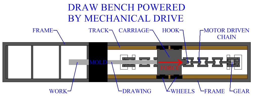
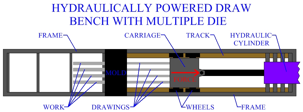
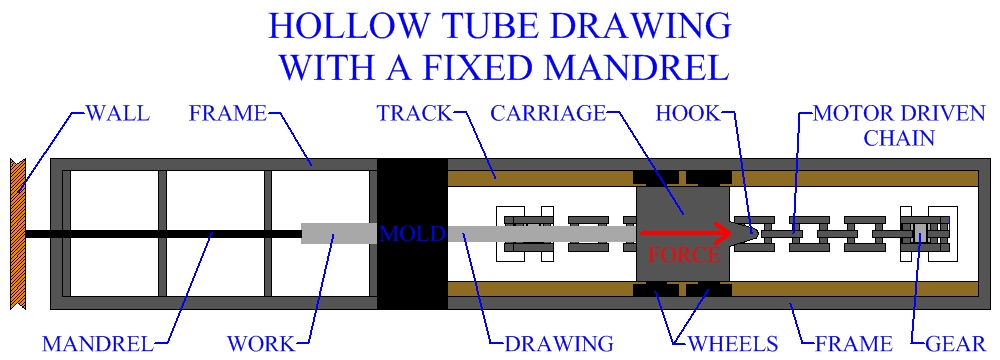
Rod or bar drawing is usually performed on a draw bench. A draw bench consists of a long table, a die stand containing the mold and a carriage used to grip and draw the work. The die stand may contain two or more molds, multiple dies allow more than one part to be drawn with each operation. Draw benches vary in size and can be up to 100 feet in length. Force used to draw the metal is exerted through hydraulic or mechanical means. Pulling force as high as 150 tons has been used during industrial production.
Figure:238
|
Figure:239
|
Production Of Hollow Tubes And Drawn Shapes
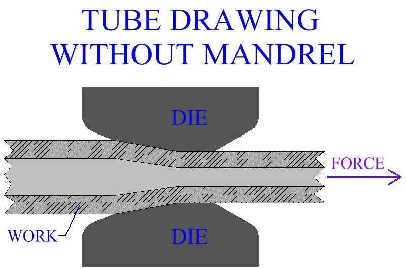
The majority of metal drawing operations produce round or square shapes, however different cross sections such as u-sections and other simple shapes are also manufactured. Hollow profiles, particularly hollow round tubes of different lengths, diameters and wall thicknesses are common in drawing production. Many tubes and special profiles are of larger geometry, and are drawn as a discrete manufacturing operation. Production of drawn shapes and hollow tubes is usually performed on a draw bench and would be classified in the rod and bar category of operations. The specifics of the metal deformation are important when drawing different cross sections. Sometimes a series of operations may be needed to form a particular profile.
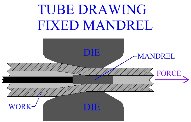
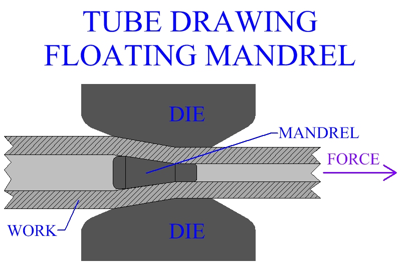
Often times drawing is used to finish tubes and profiles already manufactured by other methods, such as extrusion or rotary tube piercing. When forming a tube a mandrel may or may not be used. A tube may be formed without a mandrel if its internal dimensions are not critical. It is often required that hollow tubes hold certain tolerances on internal diameter and wall thickness. For that reason, mandrels are often employed. Fixed mandrels are anchored on one side, floating mandrels are not anchored and are designed to fit in place. Floating mandrels may allow for the production of longer lengths of tube.
Figure:240
|
Figure:241
|
Figure:242
|
Figure:243
|
Wire Drawing
Wire drawing is the second major category of metal drawing operations. While rod and bar drawing refer to the drawing of larger cross sections, wire drawing refers to the drawing of relatively smaller cross sections. The enormous amount of electrical wire and cable produced by this manufacturing method makes wire drawing a major modern industrial process. Some wire must be manufactured to tremendously small cross sectional areas, such as those used in electromagnets. Wire may be drawn to diameters as low as .0001 inch. Diamond die inserts are often used in the production of extremely fine wire.
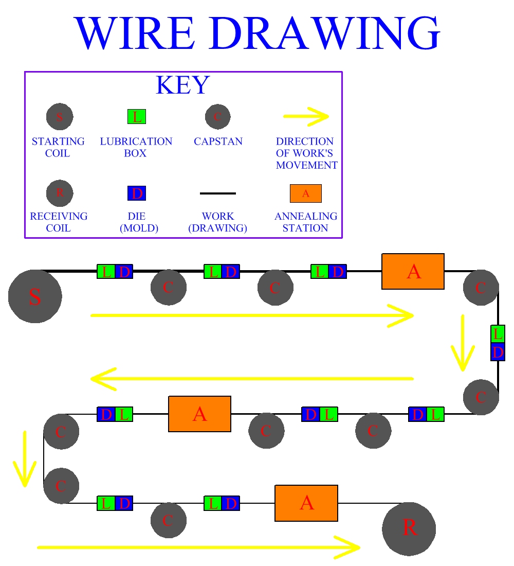
Metal work stock in wire drawing will usually undergo several reductions in diameter, since the mechanics of the process limit the amount of reduction in a single draw. This is accomplished by drawing the work through several die in series, each producing an incremental reduction in the work's diameter. Between dies the wire stock is wrapped several times around a motor driven rotating drum called a capstan, before proceeding to the next die in series. Annealing of the metal may be performed between groups of operations. The capstans provide the force for the manufacturing process. As the diameter is reduced, the speed of the wire is increased. Velocity of wire leaving the last mold in a series can be significantly higher than the velocity of the work entering the first mold. Typically drawing speeds may be 20-100 feet per minute, but in some cases wire may be drawn at 10,000 feet per minute. Pieces of stock can be end welded together as they are fed into the system of capstans and die so that the process will be completely continuous. Industrial wire drawing operations can manufacture miles of wire at a time.
Figure:244
|