SHEET METAL FABRICATION Sheet Metal Manufacturing Sheet Metal Cutting Deep Drawing Sheet Metal Sheet Metal Ironing Sheet Metal Spinning Rubberforming Sheet Metal High Energy Rate Forming Of Sheet Metal MANUFACTURING PROCESSES Metal Casting Metal Forming Metal Rolling Metal Forging Metal Extrusion Metal Drawing Powder Processes
Sheet Metal Bending
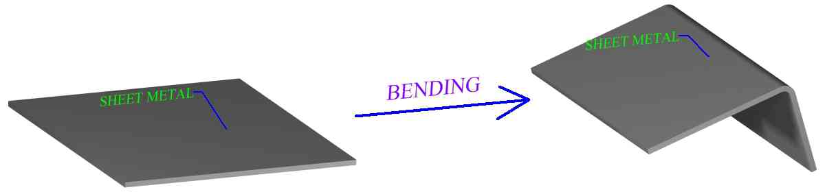
Bending of sheet metal is a common and vital process in manufacturing industry. Sheet metal bending is the plastic deformation of the work over an axis, creating a change in the part's geometry. Similar to other metal forming processes, bending changes the shape of the work piece, while the volume of material will remain the same. In some cases bending may produce a small change in sheet thickness. For most operations, however, bending will produce essentially no change in the thickness of the sheet metal. In addition to creating a desired geometric form, bending is also used to impart strength and stiffness to sheet metal, to change a part's moment of inertia, for cosmetic appearance and to eliminate sharp edges.
Figure:264
|
Metal bending enacts both tension and compression within the material. Mechanical principles of metals, particularly with regard to elastic and plastic deformation, are important to understanding sheet metal bending and are discussed in the fundamentals of metal forming section. The effect that material properties will have in response to the conditions of manufacture will be a factor in sheet metal process design. Usually sheet metal bending is performed cold but sometimes the work may be heated, to either warm or hot working temperature.
Most sheet metal bending operations involve a punch die type setup, although not always. There are many different punch die geometries, setups and fixtures. Tooling can be specific to a bending process and a desired angle of bend. Bending die materials are typically gray iron, or carbon steel, but depending on the work piece, the range of punch-die materials varies from hardwood to carbides. Force for the punch and die action will usually be provided by a press. A work piece may undergo several metal bending processes. Sometimes it will take a series of different punch and die operations to create a single bend. Or many progressive bending operations to form a certain geometry.
Sheet metal is referenced with regard to the work piece when bending processes are discussed in this section. However, many of the processes covered can also be applied to plate metal as well. References to sheet metal work pieces may often include plate. Some bending operations are specifically designed for the bending of differently shaped metal pieces, such as for cabinet handles. Tube and rod bending is also widely performed in modern manufacturing.
Bending Processes
Bending processes differ in the methods they use to plastically deform the sheet or plate. Work piece material, size and thickness are important factors when deciding on a type of metal bending process. Also important is the size of the bend, bend radius, angle of bend, curvature of bend and location of bend in the work piece. Sheet metal process design should select the most effective type of bending process based on the nature of the desired bend and the work material. Many bends can be effectively formed by a variety of different processes and available machinery will often determine the bending method.
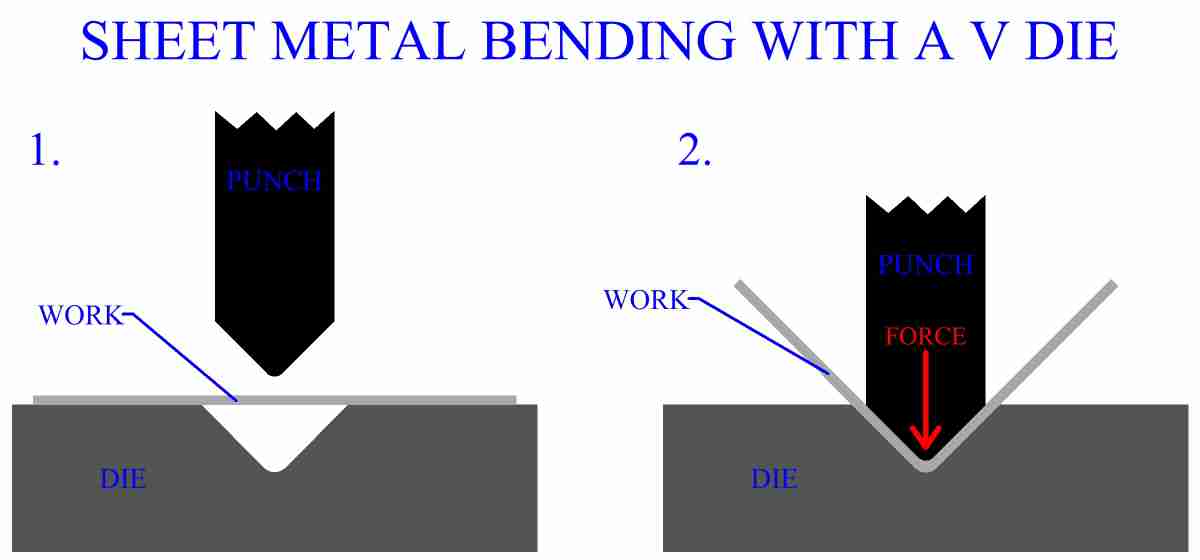
One of the most common types of sheet metal manufacturing processes is V bending. The V shaped punch forces the work into the V shaped die and hence bends it. This type of process can bend both very acute and very obtuse angles, also anything in between, including 90 degrees.
Figure:265
|
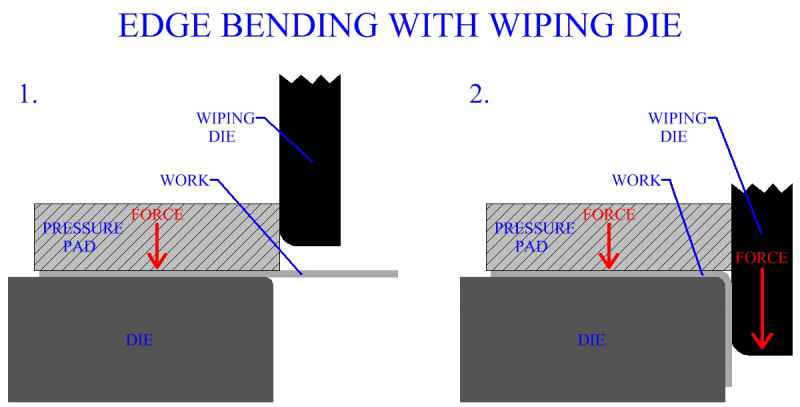
Edge bending is another very common sheet metal process and is performed with a wiping die. Edge bending gives a good mechanical advantage when forming a bend. However, angles greater than 90 degrees will require more complex equipment, capable of some horizontal force delivery. Also, wiping die employed in edge bending must have a pressure pad. The action of the pressure pad may be controlled separately than that of the punch. Basically the pressure pad holds a section of the work in place on the die, the area for the bend is located on the edge of the die and the rest of the work is held over space like a cantilever beam. The punch then applies force to the cantilever beam section, causing the work to bend over the edge of the die.
Figure:266
|
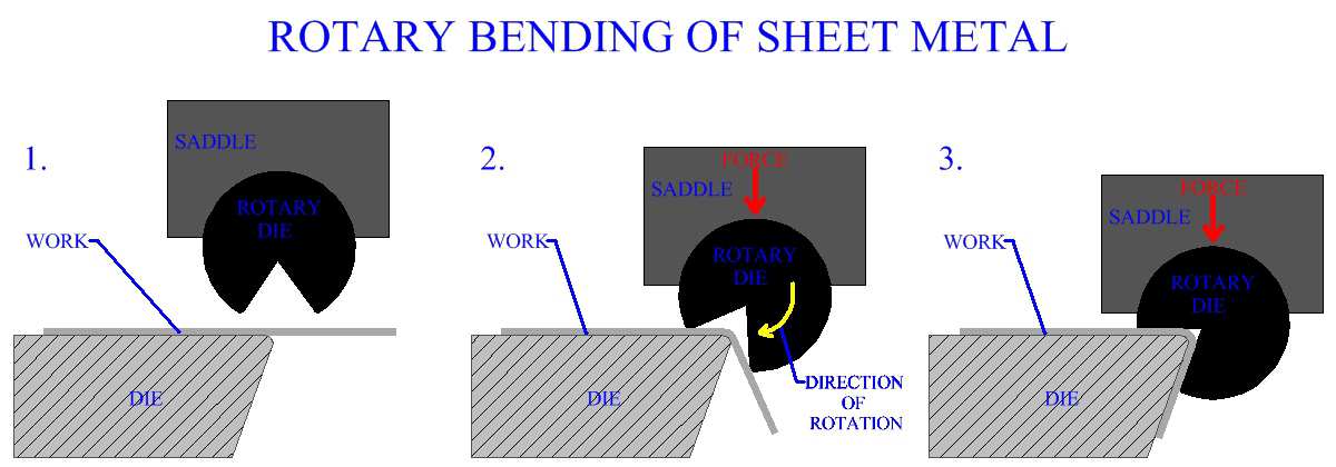
Rotary bending forms the work by a similar mechanism as edge bending. However, rotary bending uses a different design than the wiping die. A cylinder, with the desired angle cut out, serves as the punch. The cylinder can rotate about one axis and is securely constrained in all other degrees of motion by its attachment to the saddle. The sheet metal is placed cantilevered over the edge of the lower die, similar to the setup in edge bending. Unlike in edge bending, with rotary bending, there is no pressure pad. Force is transmitted to the punch causing it to close with the work. The groove on the cylinder is dimensioned to create the correctly angled bend. The groove can be less than or greater than 90 degrees allowing for a range of acute and obtuse bends. The cylinders V groove has two surfaces. One surface contacts the work transmitting pressure and holding the sheet metal in place on the lower die. As force is transmitted through the cylinder it rotates, causing the other surface to bend the work over the edge of the die, while the first surface continues to hold the work in place. Rotary bending provides a good mechanical advantage.
This process provides benefits over a standard edge bending operation, in that it eliminates the need for a pressure pad and it is capable of bending over 90 degrees without any horizontally acting equipment. Rotary bending is relatively new and is gaining popularity in manufacturing industry.
Figure:267
|
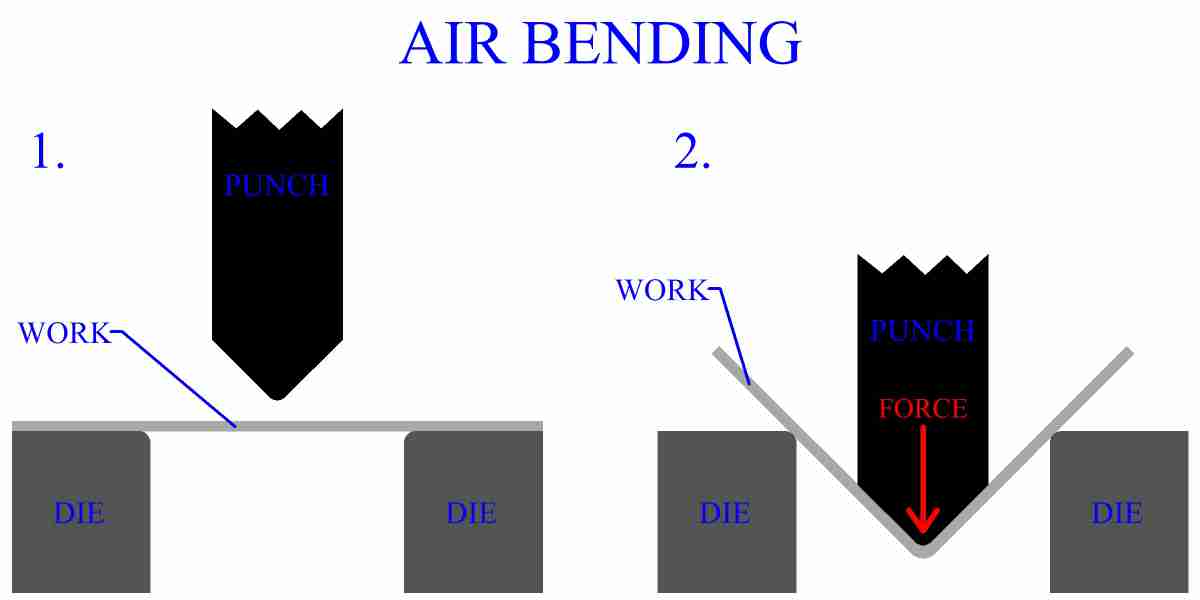
Air bending is a simple method of creating a bend without the need for lower die geometry. The sheet metal is supported by two surfaces a certain distance apart. A punch exerts force at the correct spot, bending the sheet metal between the two surfaces.
Figure:268
|
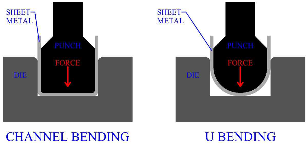
Punch and die are manufactured with certain geometries, in order to perform specific bends. Channel bending uses a shaped punch and die to form a sheet metal channel. A U bend is made with a U shaped punch of the correct curvature.
Figure:269
|
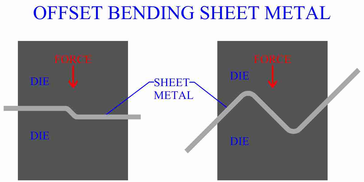
Many bending operations have been developed to produce offsets and form the sheet metal for a variety of different functions.
Figure:270
|
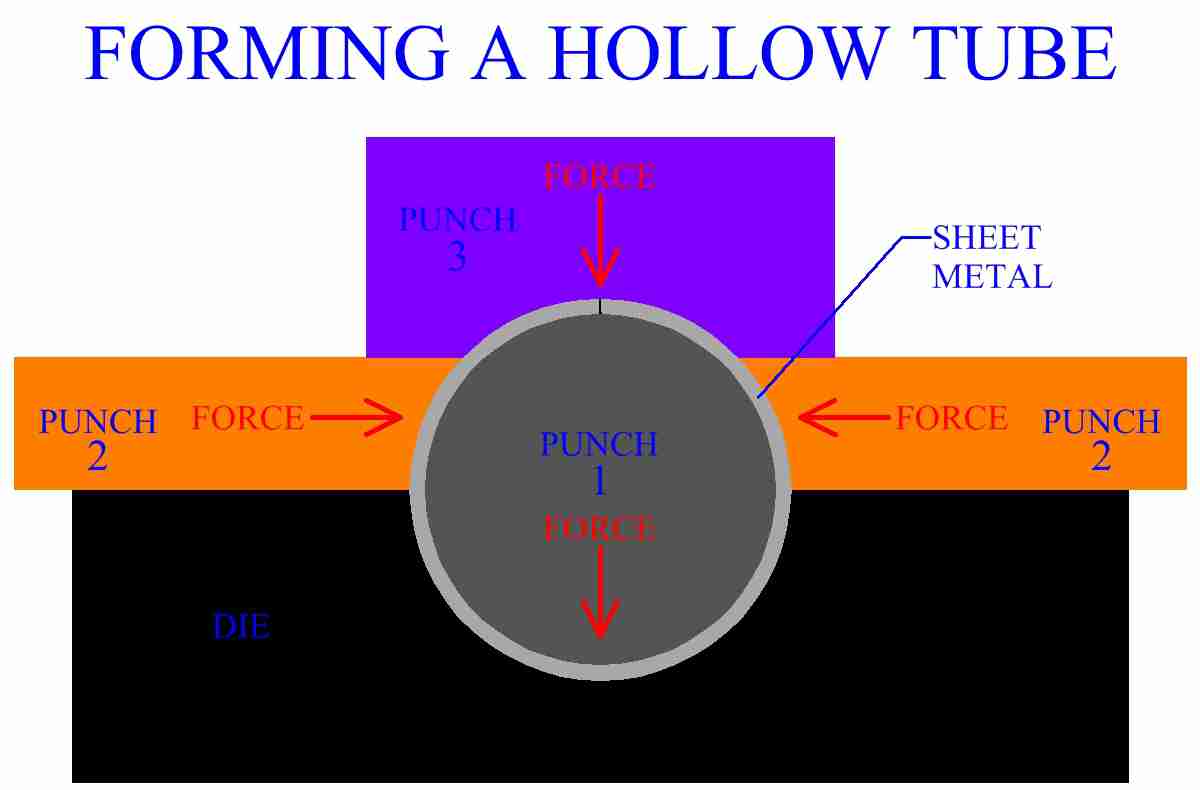
Some sheet metal bending operations involve the use of more than 2 die. Round tubes, for example, can be bent from sheet metal using a multiple action machine. The hollow tube can be seamed or welded for joining.
Figure:271
|
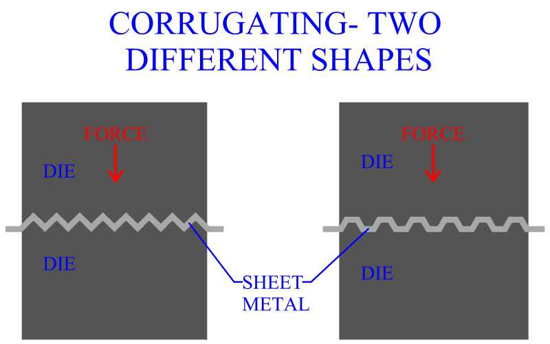
Corrugating is a type of bending process in which a symmetrical bend is produced across the width of sheet metal and at a regular interval along its entire length. A variety of shapes are used for corrugating, but they all have the same purpose, to increase the rigidity of the sheet metal and increase its resistance to bending moments. This is accomplished by a work hardening of the metal and a change in the sheet's moment of inertia, caused by the bend's geometry. Corrugated sheet metal is very useful in structural applications and is widely used in the construction industry.
Figure:272
|
Edge Bending Processes
Sheet metal of different sizes can be bent an innumerable amount of ways, at different locations, to achieve desired part geometries. One of the most important considerations in sheet metal manufacture is the condition of the sheet metal's edges, particularly with regard to the part after manufacture. Edge bending operations are commonly used in industrial sheet metal processing and involve bending a section of the metal that is small relative to the part. These sections are located at the edges. Edge bending is used to eliminate sharp edges, to provide geometric surfaces for purposes such as joining, to protect the part, to increase stiffness and for cosmetic appearance.
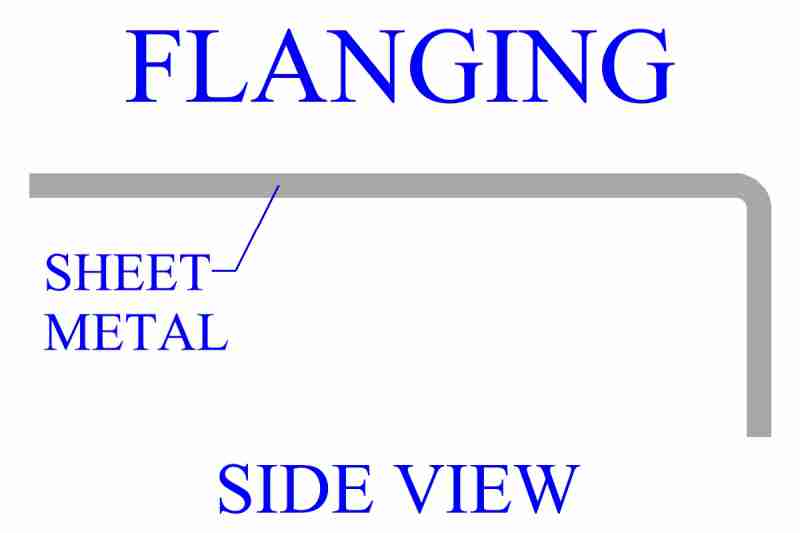
Flanging is a process that bends an edge, usually to a 90 degree angle.
Figure:273
|
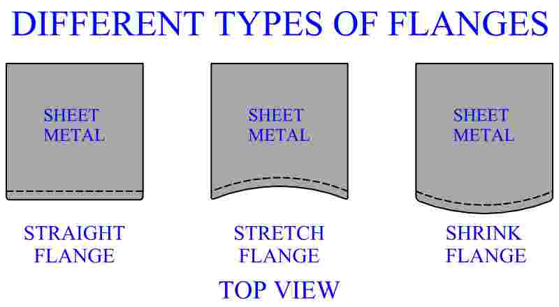
Sometimes the sheet metal's material is purposely subjected to tensions or compressions, in the processes of stretch flanging and shrink flanging respectively. In addition to bending the edge, these operations also give it a curve.
Figure:274
|
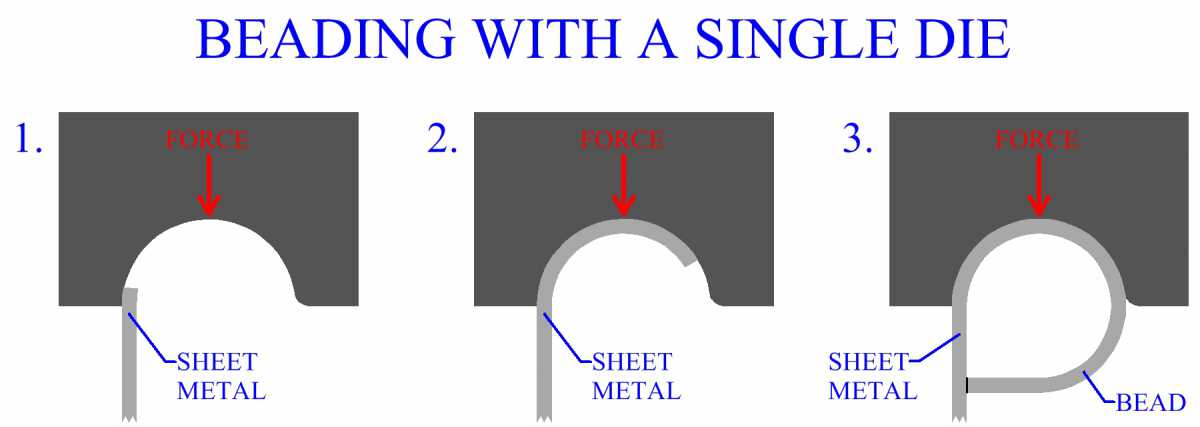
Beading is common in the edge treatment of sheet metal parts and can also be used to form the working structure of parts, such as hinges. Beading forms a curl over a part's edge. This bead can be formed over a straight or curved axis. There are many different techniques for forming a bead. Some methods form the bead progressively, with multiple stages, using several different die arrangements. Other sheet metal beading processes produce a bead with a single die. In a process called wiring, the metal's edge is bent over a wire. How the bead is formed will depend on the specific requirements of the manufacturing process and sheet metal part.
Figure:275
|
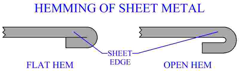
Hemming is an edge bending process in which the edge of the sheet is bent completely over on itself.
Figure:276
|
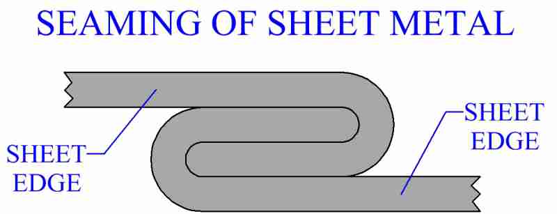
Seaming is a sheet metal joining process. Seaming involves bending the edges of two parts over on each other. The strength of the metal resists breaking the joint, because the material is plastically deformed into position. As the bends are locked together, each bend helps resist the deformation of the other bend, providing a well fortified joint structure. Double seaming has been employed to create watertight or airtight joints between sheet metal parts.
Figure:277
|
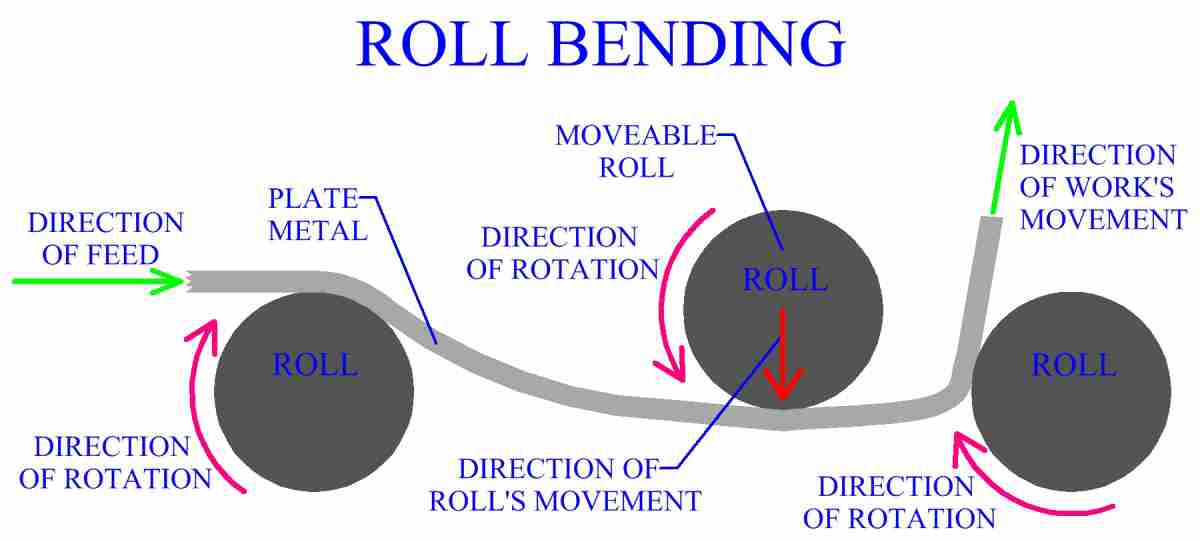
Roll Bending
Roll bending provides a technique that is useful for relatively thick work. Although sheets of various sizes and thicknesses may be used, this is a major manufacturing process for the metal bending of large pieces of plate. Roll bending uses three rolls to feed and bend the plate to the desired curvature. The arrangement of the rolls determines the exact bend of the work. Different curves are obtained by controlling the distance and angle between the rolls. A moveable roll provides the ability to control the curve. The work may already have some curve to it, often it will be straight. Beams, bars and other stock metal is also bent using this process.
Figure:278
|
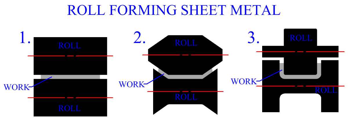
Sheet Metal Roll Forming
Roll forming of sheet metal is a continuous manufacturing process, that uses rolls to bend a sheet metal cross section of a certain geometry. Often several rolls may be employed, in series, to continuously bend stock. Similar to shape rolling, but roll forming does not involve material redistribution of the work, only bending. Like shape rolling, roll forming usually involves bending of the work in sequential steps. Each roll will form the sheet metal to a certain degree, in preparation for the next roll. The final roll completes the geometry.
Channels of different types, gutters, siding and panels for structural purposes are common items manufactured in mass production by roll forming. Rolls are usually fed from a sheet metal coil. The entry roll is supplied as the coil unwinds during the process. Once formed, continuous products can be cut to desired lengths to create discrete parts. Closed sections such as squares and rectangles can be continuously bent from sheet metal coil. Frames for doors and windows are manufactured by this method. Sheet metal coil is often roll bent into thin walled pipe that is welded together, at its seam. The welding of the continuous product is incorporated into the rolling process. Roll forming of channels is a continuous alternative to a discrete channel bending process, such as the one illustrated in figure 269. Figure 279 shows a simple sequence used to produce a channel.
Figure:279
|
This channel could be produced with a punch and die. However, in that case, the length of the channel would be limited by the length of the punch and die. Roll forming allows for a continuous part, (limited practically to the length of the sheet metal coil), that can be cut to whatever size needed. Productivity is also increased, with the elimination of loading and unloading of work. Rolls for sheet metal roll forming are typically made of grey cast iron or carbon steel. Lubrication is important and affects forces and surface finish. Sometimes rolls will be chromium plated to improve surface quality.
Mechanics Of Sheet Metal Bending
To understand the mechanics of sheet metal bending, an understanding of the material properties, characteristics and behaviors of metal, is necessary. Particularly important is the topic of elastic and plastic deformation of metal. Information on the properties of metals, with relation to manufacturing, can be found in an earlier section, (metal forming). It should be understood also that sheet metal bending produces localized plastic deformation and essentially no change in sheet thickness, for most operations. It does not create metal flow that affects regions away from the bend.
The force required to perform a bend is largely dependent upon the bend and the specific metal bending process, because the mechanics of each process can vary considerably. Proper lubrication is essential to controlling forces and has an effect on the process. In punch and die operations, the size of the die opening is a major factor in the force necessary to perform the bending. Increasing the size of the die opening will decrease the necessary bending force. As the sheet metal is bent, the force needed will change. Usually it is important to determine the maximum necessary bending force, to access machine capacity requirements.
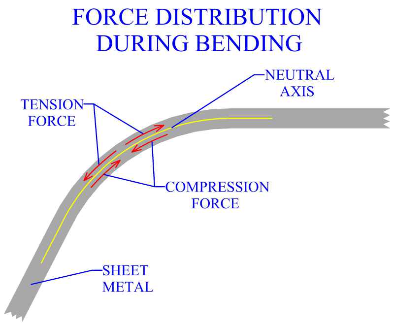
The important factors influencing the mechanics of bending are material, sheet thickness, width over which bend occurs, radius of bend, bend angle, machinery, tooling and specific metal bending process. Bending a sheet will create forces that act in the bend region and through the thickness of the sheet. The material towards the outside of the bend is in tension and the material towards the inside is in compression. Tension and compression are opposite, therefore when moving from one to the other a zero region must exist. At this zero region no forces are exerted on the material. When sheet metal bending, this zero region occurs along a continuous plane within the part's thickness, called the neutral axis. The location of this axis will depend on the different bending and sheet metal factors. However, a generic approximation for the location of the axis could be 40 percent of sheet thickness, measured from the inside of the bend. Another characteristic of the neutral axis is that because of the lack of forces, the length of the neutral axis remains the same. Fundamentally, to one side of the neutral axis the material is in tension, to the other side the material is in compression. The magnitude of the tension or compression increases with increasing distance from the axis.
Figure:280
|
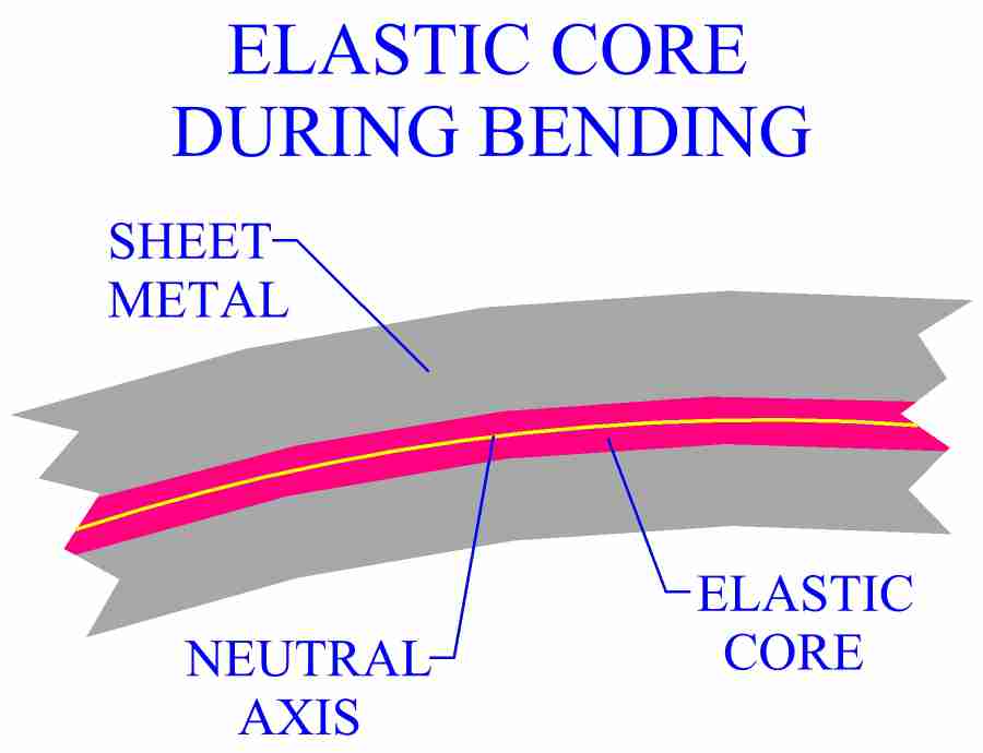
If a relatively small amount of force is exerted on a metal part, it will deform elastically and recover its shape, when the force is removed. In order for plastic deformation of metal to occur, a minimum threshold of force must be reached. The force acting on the neutral axis is zero and increases with distance from this region. The minimum threshold of force required for plastic deformation is not reached until a certain distance from the neutral axis in either direction. The material between these regions is only plastically deformed, due to the low magnitude of forces. These regions run parallel to, and form an elastic core around, the neutral axis.
Figure:281
|
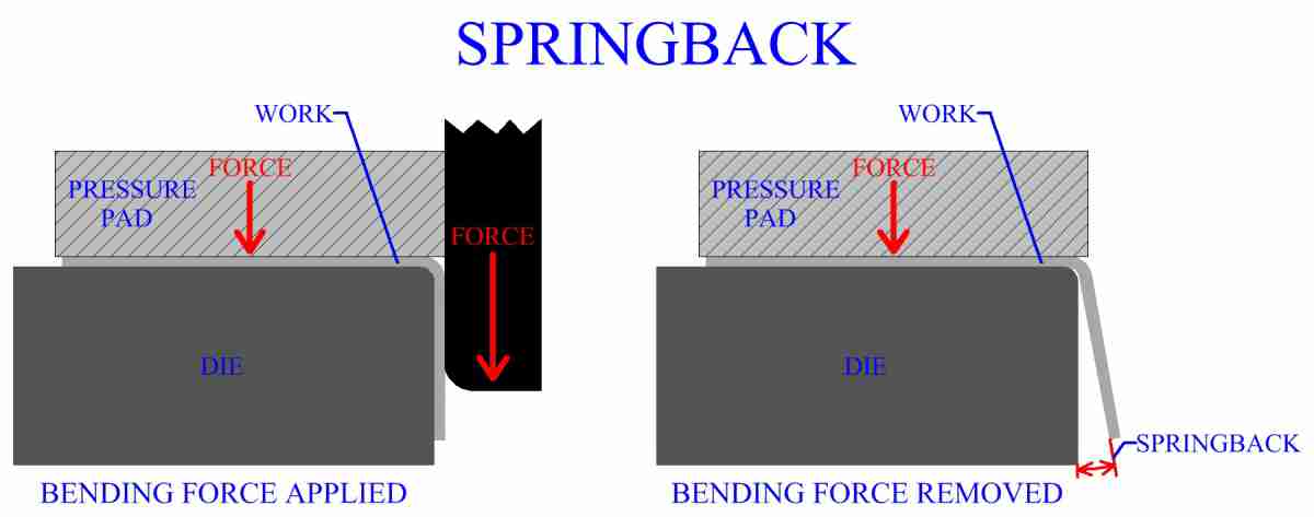
When the force used to create the bend is removed, the recovery of the elastic region results in the occurrence of springback. Springback is the partial recovery of the work from the bend to its geometry before the bending force was applied. The magnitude of springback depends largely on the modulus of elasticity and the yield strength of the material. Typically the results of springback will only act to increase the bend angle by a few degrees, however, all sheet metal bending processes must consider the factor of springback.
Figure:282
|
Methods Of Eliminating Springback
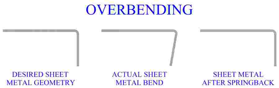
Techniques have been developed, in manufacturing industry, that can eliminate the effects of springback. One common technique is over bending. The amount of springback is calculated and the sheet metal is over bent to a smaller bend angle than needed. Recovery of the material from springback results in a calculated increase in bend angle. This increase makes the recovered bend angle exactly what was originally planned.
Figure:283
|
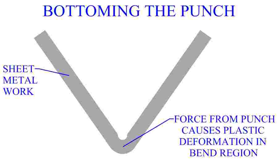
Another method for eliminating springback is by plastically deforming the material in the bend region. Localized compressive forces between the punch and die in that area will plastically deform the elastic core, preventing springback. This can be done by applying additional force through the tip of the punch after completion of bending. A technique known as bottoming, or bottoming the punch.
Figure:284
|
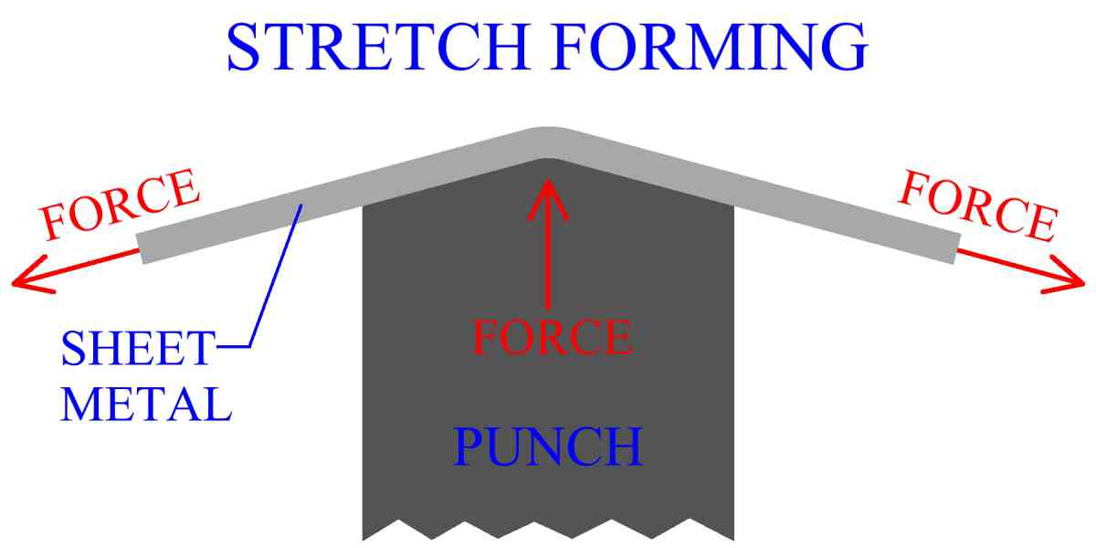
Stretch forming is a metal bending technique that eliminates most of the springback in a bend. Subjecting the work to tensile stress while bending will force the elastic region to be plastically deformed. Stretch forming can not be performed for some complex bends and for very sharp angles. The amount of tension must be controlled to avoid cracking of the sheet metal. Stretch forming is a process often used in the aircraft building industry.
Figure:285
|
Sheet Metal Bendability
Bendability of sheet metal is the characteristic degree to which a particular sheet metal part can be bent without failure. Bendability is related to the more general term of formability, discussed in the sheet metal forming section. The bendability will change for different materials and sheet thicknesses. Also, the mechanics of the manufacturing process will affect bendability, since different tooling and sheet geometries will cause different force distributions.
Metal bending tends to be a less complicated process than deep drawing in the analysis of forces acting during the operation. One simple method to quantify bendability is to bend a rectangular sheet metal specimen until it cracks on the outer surface. The radius of bend at which cracking first occurs is called the minimum bend radius. Minimum bend radius is often expressed in terms of sheet thickness, (ie. 2T, 4T). The higher the minimum bend radius, the lower the bendability. A minimum bend radius of 0 indicates that the sheet can be folded over on itself. Anisotropy of the sheet metal is an important factor in bending. If the sheet is anisotropic the bending should be performed in the preferred direction. A test to determine anisotropy is discussed in the sheet metal forming section.
The condition of a sheet metal's edges will influence bendability. Often cracks may propagate from the edges. Rough edges can decrease the bendability of a sheet metal part. Cold working at the edges, or within a part, can also reduce bendability. Vacancies within sheet metal can be another source of material failure while bending. The presence of vacancies will reduce metal bendability. Impurities in the material, particularly in the form of inclusions, can also propagate cracks and will decrease bendability. Pointed or sharply shaped inclusions are more detrimental to bendability than round inclusions. Surface quality of the sheet metal can make a difference in bending manufacture. Rough surfaces can increase the likelihood of the sheet cracking under force.
To mitigate these problems, and optimize the bendability of sheet metal, care should be taken all the way through the manufacturing process. High quality sheet metal comes from high quality metal. Effective refining techniques, along with a sound sheet metal rolling process should close up vacancies, break up or eliminate inclusions and provide a sheet metal product with a smooth surface. Edge treatment such as trimming, or fine blanking, can improve edge quality. Sometimes cold worked areas can be machined out. Annealing the part to eliminate regions of cold working and increase ductility also improves metal bendability. Bending operations are sometimes performed on heated parts, because heating will cause the metal's bendability to go up. Sheet metal may also, on occasion, be formed in a high pressure environment, which is another way to make it more bendable.
Cutting And Bending Processes
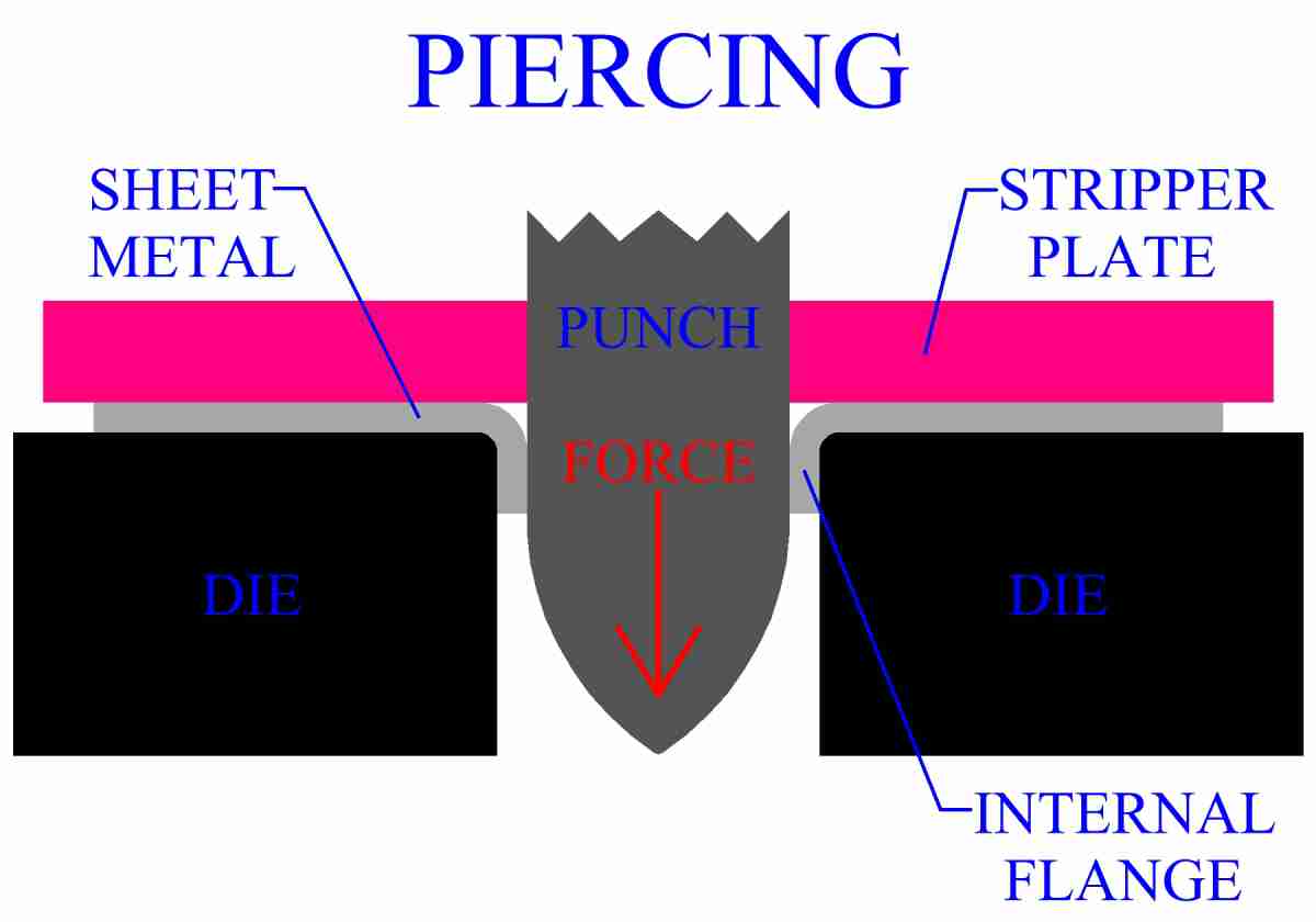
Some manufacturing processes involve both cutting and bending of the sheet metal. Lancing is a process that cuts and bends the sheet to create a raised geometry. Lancing may be used to increase the heat dissipation capacity of sheet metal parts, for example. Another common process that employs both cutting and bending is piercing. Not to be confused with the forging process of piercing. Piercing is used to create a hole in a sheet metal part. Unlike blanking, which creates a slug, piercing does not remove material. The punch is pointed and can pierce the sheet. As the punch widens the hole the material is bent into an internal flange for the hole. This flange may be useful for some applications.
Figure:286
|
Metal Tube Bulging
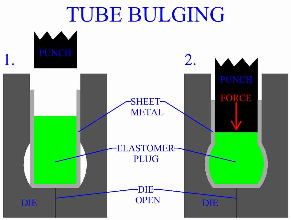
Tube bulging is a sheet metal manufacturing process in which some part of the internal geometry of a hollow metal tube is subjected to pressure, causing the tube to bulge outward. The area being bulged is usually constrained within a die that can control its geometry. Total length of the tube will be decreased because of the widening of the bulging area. There are different metal bulging techniques employed in manufacturing industry.
One main group of processes uses an elastomer plug, usually polyurethane. This plug is placed within the tube. Pressure is applied to the elastomer causing it to bulge. Expanding outward, the plug bends the sheet metal tube. Upon removal of the force, the elastomer plug returns to its original shape and can be easily removed. Polyurethane plugs are durable and will create a good pressure distribution over the surface during bending. Hydraulic pressure may also be used to produce the same bulging effect. However elastomer plugs are cleaner, easy to remove and require less complicated tooling. Split dies are used to facilitate the removal of the part.
Figure:287
|
Metal Tube Bending
Tubes, rods, bars and other cross sections are also subject to metal bending operations. It should be remembered that when bending a metal part, springback is always a factor. Several special manufacturing processes have been developed for the bending of hollow tubes. These operations can also be used on solid rods. Hollow tubes have the characteristic that they may collapse when bent. Tubes may also crack or tear, the material's ductility is important when considering tube failure.
As the bend radius goes down, the tendency to collapse increases. Bend radius in metal tube bending is measured from the tube's centerline. The other major factor determining collapse is the wall thickness of the tube. Tubes with a greater wall thickness are less likely to collapse. Bending a thick walled tube to a large radius is usually not a problem, as far as collapse is concerned. However, as wall thickness decreases and/or bend radius goes down, solutions must be found to prevent tube collapse. One solution is to fill the tube with sand before bending. Another method would be to place a plastic plug of some sort in the tube, then bend it. Both the sand and the plastic plug act to provide internal structural support, greatly increasing the ability to bend the tube without collapse.
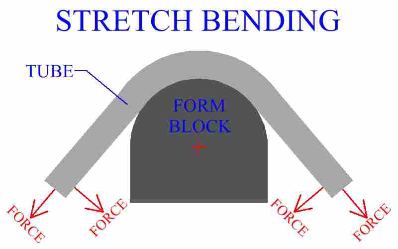
Stretch bending is a process in which a tube is formed by a stretching force parallel to the tube's axis and a simultaneous bending force acting to pull the tube over a form block. The block is fixed and the forces are applied to the ends of the tube.
Figure:288
|
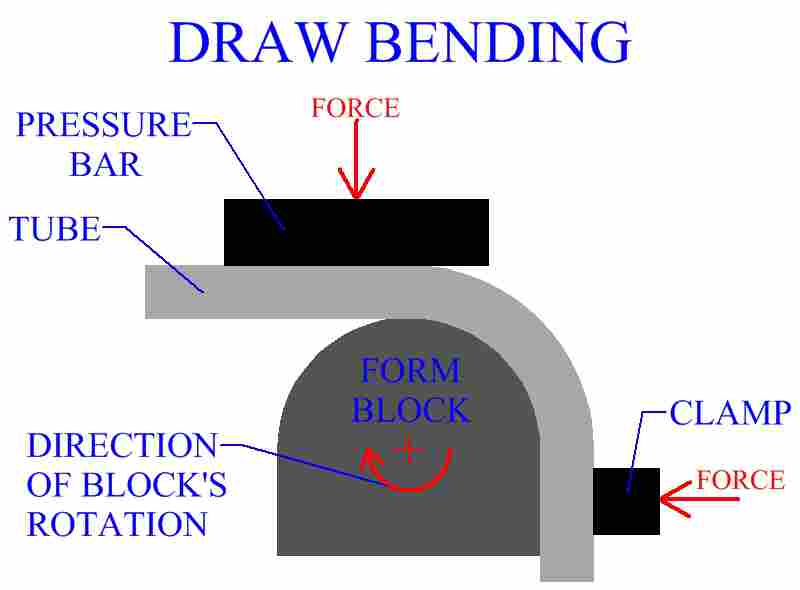
Draw bending involves clamping the tube near its end to a rotating form block. A pressure pad is also used to hold the tube stock. As the form block rotates, the tube is bent.
Figure:289
|
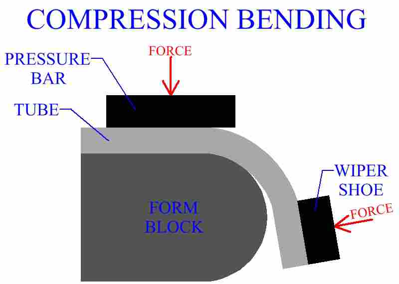
Compression bending is a tube bending process that has some similarities to edge bending of sheet metal with a wiping die. The tube stock is held by force to a fixed form block. A wiper like die applies force, bending the tube over the form block.
Figure:290
|