SHEET METAL FABRICATION Sheet Metal Manufacturing Sheet Metal Bending Deep Drawing Sheet Metal Sheet Metal Ironing Sheet Metal Spinning Rubberforming Sheet Metal High Energy Rate Forming Of Sheet Metal MANUFACTURING PROCESSES Metal Casting Metal Forming Metal Rolling Metal Forging Metal Extrusion Metal Drawing Powder Processes
Sheet Metal Cutting
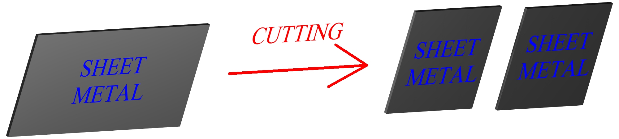
Sheet metal cutting is a major classification for many different pressworking operations. Cutting operations involve the separation of the metal of the sheet in certain areas. This separation is caused by shearing forces acting on the metal through the edges of the punch and die. Pressworking, a term referencing sheet metal operations in general, involves the working of a sheet between two die. In pressworking, the upper die is called a punch. Sheet and plate generally refers to rolled metal with a high surface area to volume ratio. The difference is that sheet metal is under 1/4 inch (6mm) in thickness, while plate metal is thicker. Most of the sheet metal cutting processes discussed can be performed on both sheet and plate metal, although for many sheet metal operations difficulties will arise with increasing plate thickness. Usually "sheet" and "sheet metal" is also referencing plate.
Figure:245
|
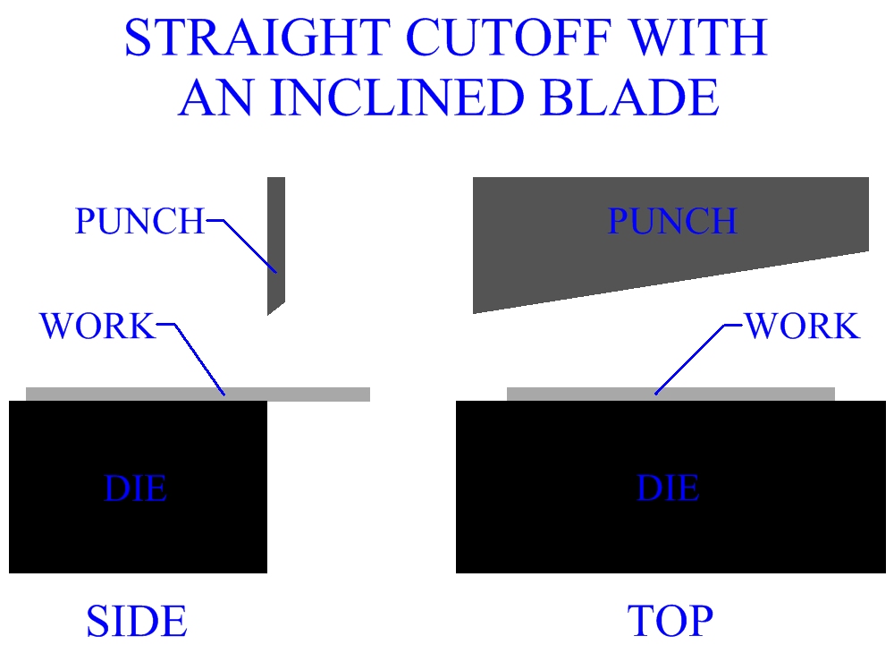
One of the simplest types of press working operations is a sheet metal cutting process called a straight cutoff. A punch separates a length of stock along a straight line. Industrial sheet metal cutting operations such as this will usually incline the punch so as to reduce the maximum force needed by distributing the required force over the cutting stroke. The angle that the punch may be inclined varies from 4 to 15 degrees, however the higher the angle, the greater the magnitude of the horizontal force component acting to displace the work. For that reason angles are usually under 9 degrees. The metal sheet is fed through after each cutoff and the process can be repeated very quickly.
Figure:246
|
Cutoff And Parting Of Sheet Metal
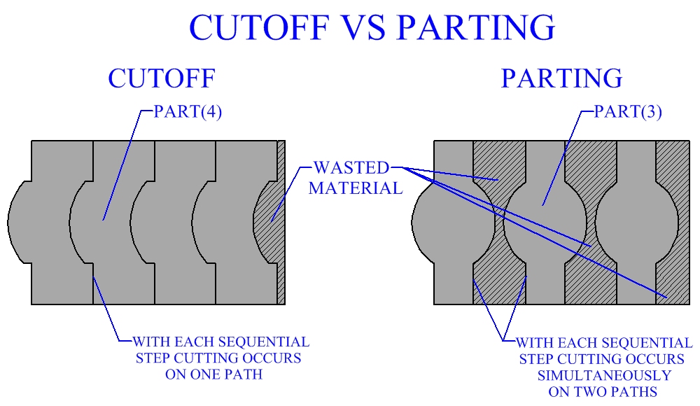
Cuttoffs and partings are important basic sheet metal cutting processes performed in manufacturing industry. Cutoffs need not be straight, rather they may be over several lines and/or curves. Partings are similar, in that a discrete part is cut from a sheet or strip of metal along a desired geometric path. The difference between a cutoff and a parting is that a cutoff can be nestled perfectly on the sheet metal, due to its geometry. With cutoffs, the cutting of sheet metal can be done over one path at a time and there is practically no waste of material. With partings, the shape can not be nestled precisely. Partings involve cutting the sheet metal along two paths simultaneously. Partings waste a certain amount of material, that can be significant.
Figure:247
|
Punching And Slotting
Punching is also a basic sheet metal cutting process, that has many different forms and applications in pressworking manufacture. Punching involves cutting out a piece of material from a metal sheet. The material removed may be round or some other shape. This excess metal, once punched out, is called a slug and is usually discarded as scrap. Slotting is a type of punching operation. Slotting refers specifically to the punching of rectangular or elongated holes.
Blanking Of Sheet Metal
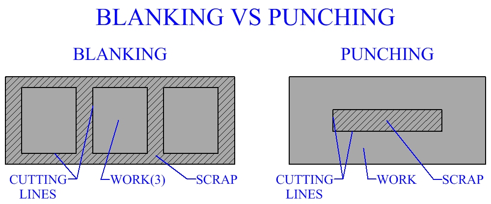
Blanking is the cutting of a sheet metal part along a closed contour in one step. The piece cut out is called a blank and may be further processed. Many blanks are often continuously cut out of a sheet or strip. Blanking will waste a certain amount of material. When designing a sheet metal blanking process, the geometry of the blanks should be nestled as efficiently as possible to minimize material waste. A distinction should be made between the two sheet metal cutting processes of blanking and punching, since essentially they are the same process. In punching, the piece cut out is waste. In blanking, the piece cut out is the work and is kept.
Figure:248
|
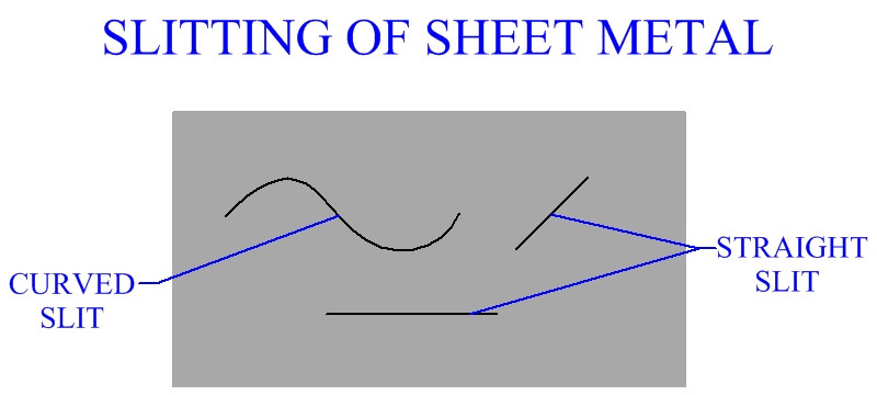
Sheet Metal Slitting
Slitting is a shearing process in which the sheet metal is cut by two opposing circular blades, like a can opener. Slitting can be performed in a straight line or on a curved path. The circular sheet metal cutters can be driven, or the work may be pulled through idle cutters. Slitting usually produces a burr that must be removed.
Figure:249
|
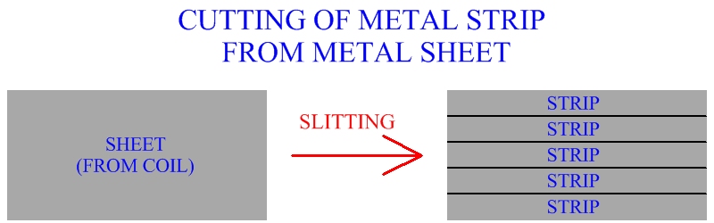
Slitting is often an important sheet metal cutting process, performed early in the processing of manufactured parts. Pressworking machines and die may require a strip of a certain width. Sheet metal usually arrives to the factory in coil, (see metal rolling ). These sheets are usually much wider than needed and are cut into strips of desired width by slitting. Sheet metal coil can be cut into many strips at once, by several simultaneous slitting operations. These strips provide sheet metal stock for further pressworking processes.
Figure:250
|
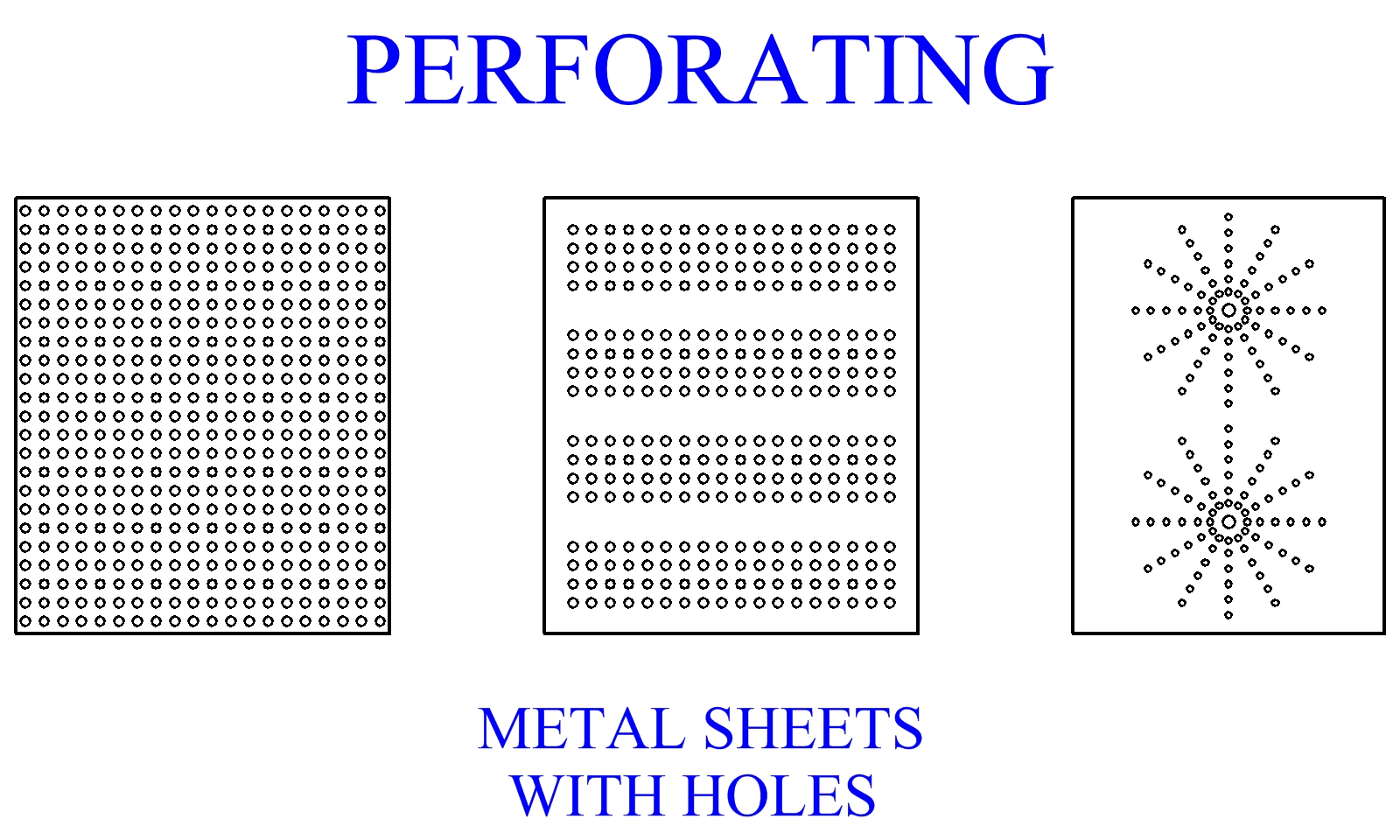
Perforating Of Sheet Metal
Sometimes it is desirable to punch many holes in a piece of sheet metal, often in a certain pattern. These holes may be round or some other shape. Perforating sheet metal will allow for the passage of light or fluid material through the sheet. It can often serve in ventilation and filtration of fluid substances. Perforated sheet metal is also used in structure and machine construction, to reduce weight and for cosmetic appearance. Special equipment is employed that punches many holes at once, at a high rate. In industrial manufacturing practice, the size of these holes is usually from .04 inches to 3 inches, (1-75mm). The upper rate at which some special perforating machines can punch holes is 100,000 to 300,000 per minute.
Figure:251
|
Notching And Seminotching
Notching is a sheet metal cutting process that involves the removal of material from a work piece, starting at the edge and cutting inward. The objective of notching is to create a sheet metal part with a desired profile. Notching is often performed as a progressive process, each operation removing another piece to make the correct contour. Seminotching is the removal of sheet metal material that is not located at the edge of the work. Seminotching is practically identical to punching. The difference is that seminotching is part of a progressive cutting operation, in the creation of a specific profile.
Progressive Processing In Sheet Metal Manufacturing
Progressive processing, as employed in manufacturing products, is performing a series of sequential operations each of which contributes progressively towards the creation of a manufactured part. Often the order in which the operations occur is important. Sheet metal manufacturing is a good example of an industry that uses a large amount of progressive processing. Notching, as discussed, is generally a progressive process in the creation of a profile. Many other sheet metal cutting operations may occur in a larger progressive process. The complete process may also include bending and/or drawing, as cover in latter pages. Progressive processing of sheet metal is also discussed further in the cutting molds section, (see figure 261).
Nibbling
Punches for the cutting of holes and profiles in sheet metal may come in many different shapes and sizes. A machine called a nibbler uses a small straight punch to create the same geometric removal of sheet metal as that of a larger more complicated punch. It does this by rapidly punching many overlapping holes to make the larger cut profile. Nibbling is useful in producing intricate cuts with simple machinery. Nibbling may take longer than a punch specifically designed for a certain cut, however it may be an efficient alternative for small production runs.
Mechanics Of Cutting Sheet Metal
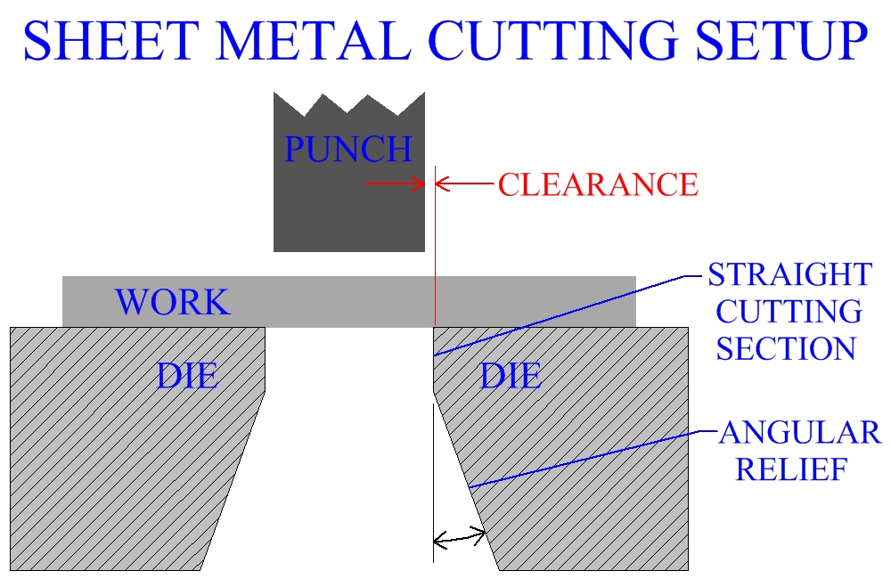
Mechanics of cutting sheet metal should be understood when designing a pressworking manufacturing process. The work piece in a sheet metal cutting operation is secured to the lower die, while the motion of the upper die, (called a punch), enacts the cutting. Edges of the punch and die do not line up precisely, due to a clearance or space between them. The punch is designed to enter the matching hole in the lower die and is always at least a little smaller. Clearance size, in sheet metal cutting, will vary with different process factors and its selection will affect the quality of the manufactured part.
Figure:252
|
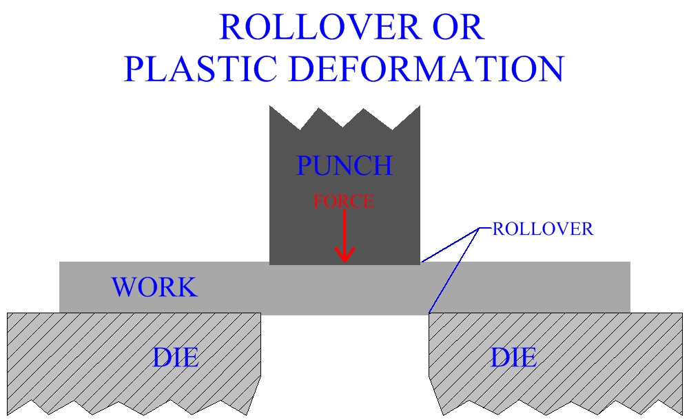
As the cutting process begins, force enacted through the punch causes it to move toward the work. The sheet metal is secured to the lower apparatus, it does not move when contacted by the punch. Instead, pressure builds up between the punch and sheet. Plastic deformation of the surface metal occurs. This happens at the top and bottom surfaces, since the bottom cutting die is pushing up with the same force that the punch is pushing down. In manufacturing practice, the plastic deformation occurring at the surfaces of the sheet metal, at this stage in the cutting operation, is referred to as rollover.
Figure:253
|
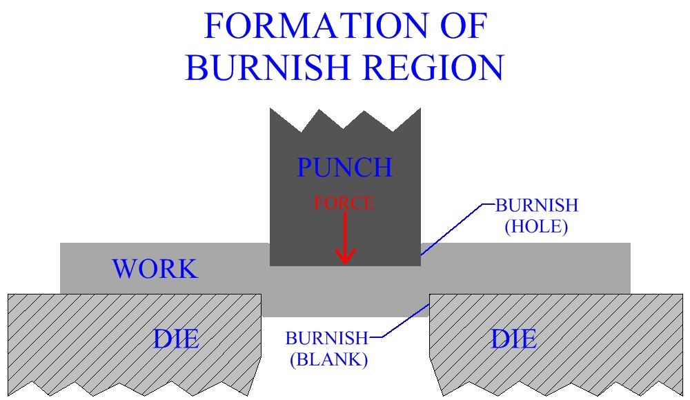
Penetration occurs next, the actual cutting of sheet metal begins, as the force causes the punch and die to sink into the work material. This creates a penetration zone, known as the burnish or burnish region. This burnish region may typically occupy 30% to 60% of the total thickness of the sheet. Actual thickness of this straight, smooth surface region is dependent upon several factors. The more ductile the metal, the greater the thickness of the burnish relative to total sheet thickness. Increases in clearance or total sheet thickness will decrease the percent of burnish region. Burnish zones on the hole in the sheet metal occur at the top. On the metal removed, (slug or blank), the burnish zone will occur at the bottom. Concern over the edge quality of the metal cut or the hole depends on if the sheared material is a slug or blank.
Figure:254
|
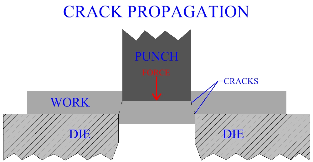
At some point during the sheet metal cutting operation, when a certain depth of punch penetration is reached, the forming of the burnish region ends with crack propagation. This occurs from the edges of the punch, on the top, and from the edges of the die, on the bottom.
Figure:255
|
In a well designed sheet metal cutting process, the cracks should meet each other and form a continuous break. This break will create the fracture region. The fracture region starts at the end of the burnish region and occupies most of the rest of the thickness of the cut, with exception to the burr. Greater clearance, greater sheet thickness and less ductility of the metal will increase the proportion of the fracture region relative to the total sheet thickness.
Figure:256

|
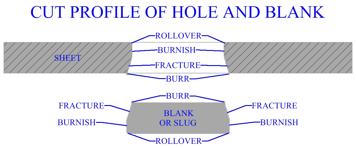
The burr is a thin ridge of material that is formed due to the elongation of metal during the final separation of the sheet. More ductile metals tend to form larger burrs. In manufacturing practice, sharp tools can mitigate burrs. Examination of the edge surfaces of cut sheet metal will display differences between the burnish region and the fracture region. The burnish zone is straight and has a smooth surface, while the fracture zone is angled and has a rough surface.
All surface zones of cut sheet metal occur in the opposite order on the sheet than on the blank or slug. For example, the burr forms on the bottom edge of the cut hole, while it forms on the top edge of the blank. Edge quality of cut sheet metal is very important in pressworking manufacture. One consideration is the amount of cold working that might have been experienced by the work metal at different areas around the cutting surface. This would vary and be a result of material deformation that occurred during the operation. The angles, roughness and features of the edge's surface would also be a consideration. Cutting factors have much to do with sheet metal edges, for example a larger burnish zone would be indicative of a better edge surface quality. A large variety of deburring, chamfering, bending and other secondary processing operations may be employed to produce sheet metal product with edges of the desired geometry and quality.
Figure:257
|
Clearance During A Cutting Process
Clearance is an important factor in the design of a sheet metal cutting process. As discussed earlier, cutting clearance is the straight line, lateral distance between the edge of the punch and the edge of the die hole. The way the metal separates, hence the cut, will be largely determined by the clearance. Optimization of cutting clearances, dependent upon specific process factors, will provide a quality cut. When clearances are correctly employed, the mechanics of sheet metal cutting should occur as described in the preceding section.
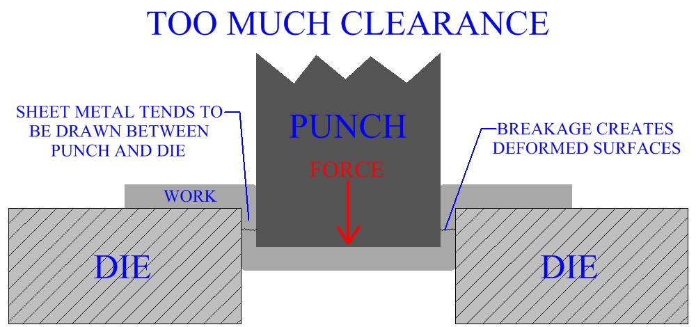
Improper values could compromise the cutting process. More clearance than required causes the sheet metal to get forced between the cutting edges. Fracture occurs incorrectly and the resulting edge is usually not desirable.
Figure:258
|
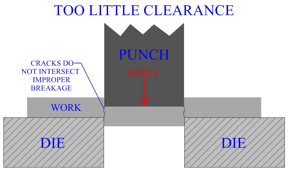
If not enough cutting clearance is provided, the fracture lines propagating from the punch and die will not line up. Noncontinuous fracture lines, in the sheet metal, usually result in secondary shearing and a deformed edge surface.
Figure:259
|
The greater the sheet metal thickness, the higher the clearance value should be. In manufacturing industry there is a range of optimum values for specific processes, clearances may span from 1% to 30% of sheet thickness. Generally, typical values span from 3% to 8% of sheet thickness. A large factor is the type of work material and its temper. Aluminum alloy sheet metal might have an optimum clearance value of 4%, a brass sheet 6% and a hard steel sheet 7.5%. If the hole size is small relative to total sheet thickness, extra clearance could be needed.
The sheet metal cutting clearance value may be added to either the punch or die, depending on if it is a blanking or a punching operation. Basically, given a certain size, does the hole have to be that size or is it important that the blank be that size. For a blank of a certain size the hole in the die should be the correct size, therefore, subtract the clearance from the punch. In blanking, the punch will be smaller than the desired blank size. When punching, for a hole of a certain size, the punch should be the correct size. In this case the clearance is added to the hole in the die making it larger than the desired hole size.
Cutting Considerations
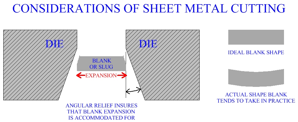
Lubrication is an important factor in maintaining sheet metal cutting molds. Sheet cutting operations are powered mainly by mechanical presses, the crank press is often used, (see presses). The lower die are straight near the top of the hole, then an angular clearance is provided to allow for the expansion of the blank or slug after it is forced out of the hole. Another consideration concerning the blank or slug is its tendency to warp, due to the forces involved during the cutting process.
Figure:260
|
Sheet Metal Cutting Molds
The mold for sheet metal cutting consists of the punch and die, as discussed. Punch and die material is usually tool steel or sometimes carbides. Some molds will allow for the performance of several operations at once with a single movement. These are termed compound die. Often a work piece will undergo a series of operations at different die. The work is transferred from one die to another after each operation is complete. These transfer die are sequenced and aligned together in such a way as to constitute the larger process.
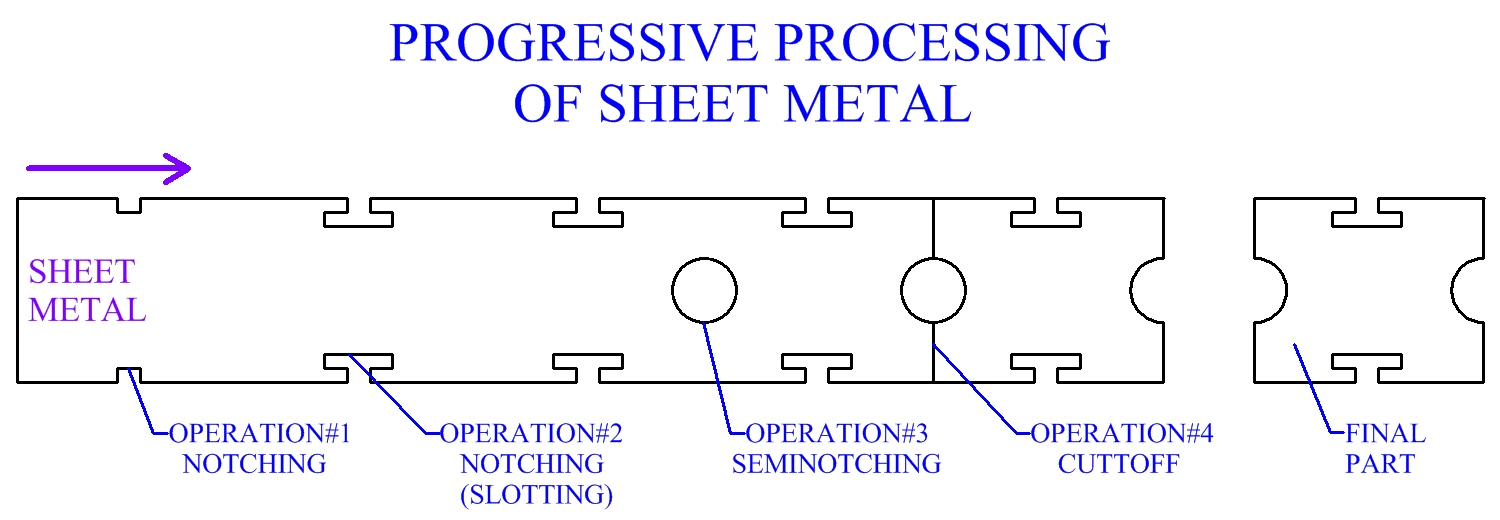
Progressive die allow for many different sequential operations that could be performed at several stations, to be performed at a single die. The operations are lined up linearly, in the direction of feed. With every stroke each operation is performed once. The work is incremented forward a step, each step being a constant distance. With each step, each section of sheet metal will experience the next operation in line. Bending or drawing operations may also be incorporated along with cutting in a larger progressive process. The sheet metal sections stay attached to the original strip while these operations are occurring. All operations will occur once on each individual section. The last operation cuts the section from the strip. Each section, when removed, comprises an individual part.
Figure:261
|
Cutting Forces In Sheet Metal Manufacture
The amount of cutting force required is a critical factor when selecting machinery, during sheet metal process design. The maximum amount of force needed will gauge if the machine's capacity is adequate for the manufacturing process. Often the machinery capacity far exceeds the necessary force for a particular operation. In many cases a rough approximation of the maximum required force for a sheet metal cutting operation can define the sufficiency of available machinery. Without including clearance or friction, maximum force required for a sheet metal cutting operation can be estimated by: Forcemax = (Length Of Cut)(thickness)(Ultimate Shear Strength). Forcemax is the maximum force required for the operation. Length of cut is the length of the perimeter of the area of sheet metal to be removed. Thickness is the thickness of the sheet. The ultimate shear strength of the work material can be referenced and is usually about 70%-80% of the ultimate tensile strength.
There are solutions employed in manufacturing industry for cases of inadequate tonnage capacity. Punches or dies for sheet metal cutting may be beveled, reducing force by distributing the cut over a length of the stroke. Parts may be redesigned for manufacture, or a different work material used. Larger cuts can be divided into several smaller cuts that require less force, but ultimately remove the same material. Another alternative is to use higher capacity machinery.
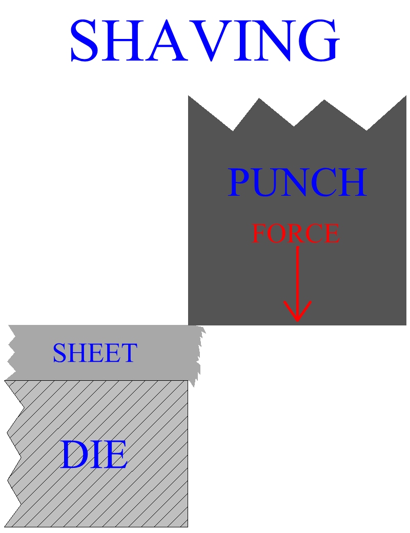
Shaving
Edge surfaces of cut sheet metal are not typically smooth and straight. Even in properly cut metal, the fracture zone will be angled and rough. In sheet metal cutting, the lower the clearance value the higher the edge's quality. Shaving is a secondary process that can be used to improve edges of cuts that have already been made. Shaving uses very little clearance to perform a straight, smooth, accurate cut to only the end of the edge. Shaving is a chip removal type process and should not be used to cut large amounts of material.
Figure:262
|
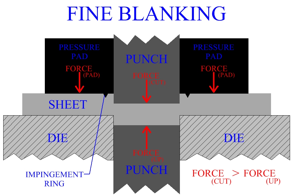
Fine Blanking Of Sheet Metal
It is possible to employ fine blanking for many sheet metal cutting operations, particularly those involving lower total sheet thickness. Fine blanking is an advanced precision pressworking process that can create cuts having close tolerances and straight smooth edges, without shaving or other secondary processes.
A press forces a pressure pad on the sheet metal, holding the work tightly between the lower die and the pressure pad. Close to, outside and all around the edge of the cut, a v-shaped ring projecting from the bottom of the pressure pad impinges the work piece. This further secures the work from movement and restricts metal flow. The cutting punch for this operation has a very small clearance with the lower die, usually 1%. As pressure is applied to the work, the punch cuts through the metal at a slow rate. Simultaneously, another punch applies force to the other side of the sheet in the opposite direction. The secondary punch delivers less force than the cutting punch. Its purpose is to help with the cut and to prevent warping of the bank, a common problem in sheet metal blanking operations. The force of the support punch is less than and in the opposite direction of the cutting punch, therefore the summation of both vectors indicates that the total force, (and hence the movement), will be in the direction dictated by the cutting punch. Fine blanking of sheet metal will employ a triple action press. These presses are usually hydraulic and each action can be controlled individually.
Figure:263
|
Other Sheet Metal Cutting Processes
In manufacturing industry, other methods are also employed for the cutting of sheet metal, (and plate). Particularly in the primary cutting process of converting the initial sheet to strip. Flame cutting is popular and can cut through thick plates. Sawing, such as with a band saw, is a machining process that can also cut thick plates. Sawing, like other machining operations, is a material removal process. Laser beam cutting uses lasers to cut sheet metal. Laser beam cutting can be computer controlled and produce very accurate cuts. Water jet machining is also used in the cutting of metal. In water jet machining, a powerful, concentrated jet of water provides the force for the cutting operation.