| Manufacturing Home
METAL CASTING
PROCESSES
Metal Casting Principles
Metal Casting
Metal Casting Operation
Effect Of Gases On Metal Casting
Expendable Mold Casting
Sand Casting
Plaster Mold Casting
Ceramic Mold Casting
Shell Mold Casting
Vacuum Casting or V-process
Expanded Polystyrene Casting
Investment Casting
Permanent Mold Casting
Basic Permanent Mold Casting
Slush Casting
Pressure Casting
Vacuum Permanent Mold Casting
Die Casting
Hot Die Casting
Cold Die Casting
True Centrifugal Casting
Semicentrifugal Casting
Centrifuge Casting
Ingot Casting
Continuous Casting
MANUFACTURING
PROCESSES
Metal Forming
Metal Rolling
Metal Forging
Metal Extrusion
Metal Drawing
Sheet Metal
Powder Processes
|
Metal Casting Design
Mold and Gating System Design, Directional Solidification, and Troubleshooting
In the previous sections we discussed the fundamental aspects of manufacturing parts
by metal casting. We covered the creation of patterns, and the setup of the mold and gating system. Also
we discussed the metal casting operation itself, including the pouring of the molten material into the mold,
the elements and functions of the different parts of the mold during the manufacture of the cast part, and the
problems and possible defects encountered during the employment of the manufacturing process of metal casting. In this
section we will examine the specifics of good mold and gating system design in order to manufacture higher quality
metal castings and minimize defects that may occur during the casting process. This section will be useful to those
designing a system to manufacture a part by metal casting, or to help as a troubleshooting guide for improvement upon
an existing system.
Gating System and Mold Design:
When selecting to manufacture a part by casting one must consider the material properties and possible defects
that this manufacturing process produces. The primary way to control metal casting defects is through good mold design
considerations in the creation of the casting's mold and gating system. The key is to design a system that promotes
directional solidification. Directional solidification, in casting manufacture, means that the material will
solidify in a manner that we plan, usually as uniformly as possible with the areas farthest away from the supply
of molten metal solidifying first and then progressing towards the risers. The solidification of the casting must
be such that there is never any solid areas that will cut off the flow of liquid material to unsolidified areas
creating isolated regions that result in vacancies within the casting's material, as discussed
in the Metal Casting Operation section and shown in Figure 14.
It is important to create an effective manufacturing process. Gating system design is crucial in controlling
the rate and turbulence in the molten metal being poured, the flow of liquid metal through the gating system,
and the temperature gradient within the metal casting. Hence a good gating system will create directional
solidification throughout the casting, since the flow of molten material and temperature gradient will determine
how the metal casting solidifies.
When designing a mold for a metal casting or trying to fix or improve upon and existing design you may want to
consider the following areas.
Insure that you have adequate material: This may seem very obvious, but in the
manufacturing of parts many incomplete castings have been a result of insufficient material. Make sure that that
you calculate for the volume of all the areas of your casting, accounting for shrinkage.
Consider the Superheat: Increasing the superheat, (temperature difference
between the metal at pouring and freezing), as mentioned previously can increase fluidity of the material for the
casting, which can assist with its flow into the mold. This causes a compromise to the manufacturing process.
Increasing the superheat has problems associated with it, such as increased gas porosity, increased oxide formation,
and mold penetration.
Insulate Risers: Since the riser is the reservoir of molten material for the
casting, it should be last to solidify. Insulating the top as mentioned earlier, shown in figure 13, will greatly
reduce cooling in the risers from the steep temperature gradient between the liquid metal of the casting, and the
the room temperature air.
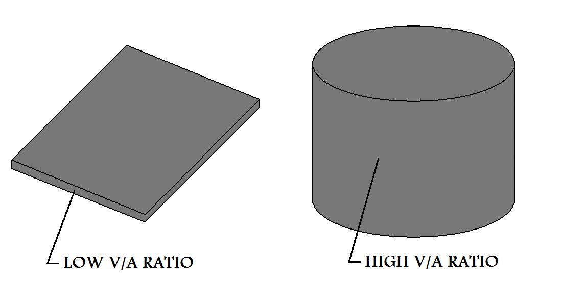
Consider V/A Ratios: In casting manufacture, V/A ratio stands for volume to
surface area or mathematically (volume/surface area). When solidification of a casting begins a thin skin of
solid metal is first formed on the surface between the casting and the mold wall. As solidification continues
the thickness of this skin increases towards the center of the liquid mass. Sections in the casting with low
volume to surface area will solidify faster than sections with higher volume to surface area. When manufacturing
a part by metalcasting consideration of the of V/A ratios is critical in avoiding premature solidification of the
casting and the formation of vacancies.
Figure:15
|
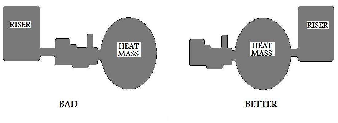
Heat Masses: Avoid large heat masses in locations distant to risers. Instead,
locating sections of the casting with low V/A ratios further away from the risers will insure a smooth
solidification of the casting.
Figure:16
|
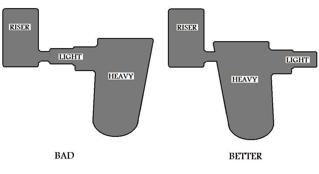
Sections of the Casting: The flow of material is very important to the
manufacturing process. Do not feed a heavy section through a lighter one.
Figure:17
|
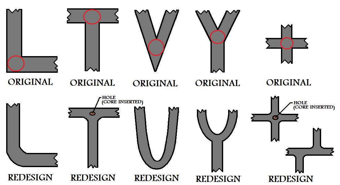
Be Careful With Consideration To L,T,V,Y and + junctions: Due to the
nature of the geometry of these sections it is likely that they will contain an area where the metal casting's
solidification is slower than the rest of the junction. These hot spots are circled in red in Figure 18.
They are located such that the material around them, which will undergo solidification first, will cut off the
hot spots from the flow of molten metal. The flow of casting material must be carefully considered when
manufacturing such junctions. If there is some flexibility in the design of the metal casting and it is possible you may
want to think about redesigning the junction. Some possible design alternatives are shown in Figure 18. These should
reduced the likelihood of the formation of hot spots.
Figure:18
|
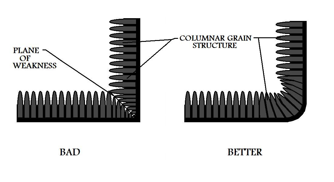
Prevent Planes of Weakness: When metal castings solidify, columnar grain structures
tend to develop, in the material, pointing towards the center. Due to this nature, sharp corners in the casting may
develop a plane of weakness. By rounding the edges of sharp corners this can be prevented.
Figure:19
|
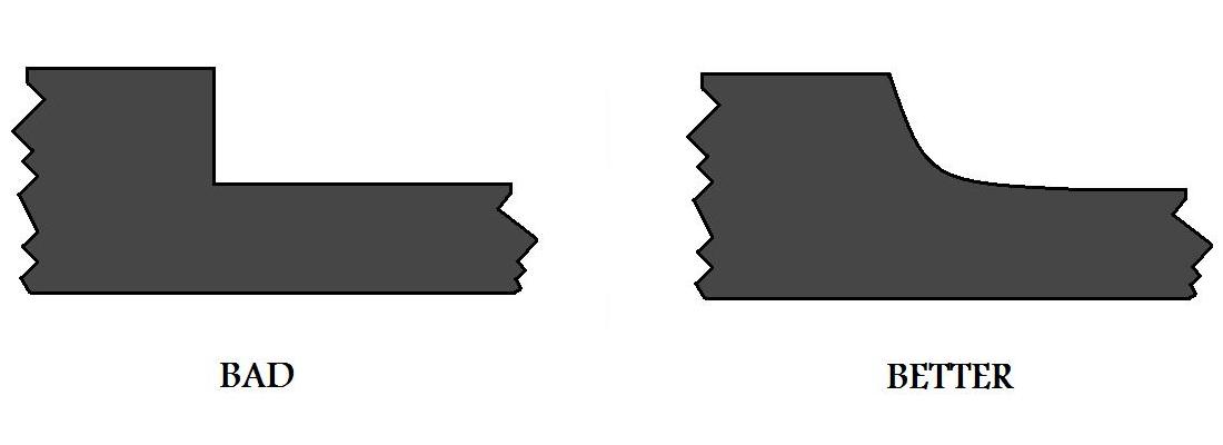
Reduce Turbulence: When manufacturing a metal casting, turbulence is always a factor
in our flow of molten metal. Turbulence, as covered earlier in the pouring section, is bad because it can
trap gases in the casting material and cause mold erosion. Although not altogether preventable in the manufacturing
process, turbulence can be reduced by the design of a gating system that promotes a more laminar flow of the
liquid metal. Sharp corners and abrupt changes in sections within the metal casting can be a leading cause of turbulence.
Their affect can be mitigated by the employment of radii.
Figure:20
|
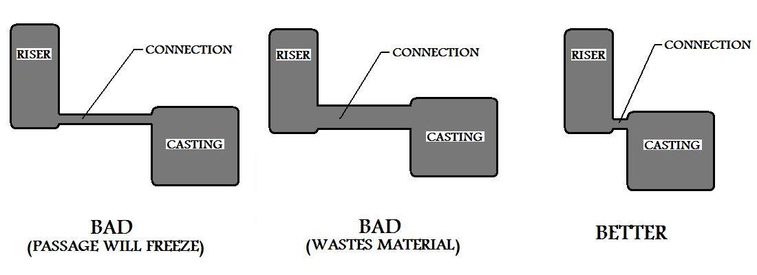
Connection Between Riser and Casting Must Stay Open: Riser design is very
important in metal casting manufacture. If the passage linking the riser to the metal casting solidifies before the
casting, the flow of molten metal to the casting will be blocked and the riser will cease to serve its function.
If the connection has a larger cross sectional area it will decrease its time to freeze. Good manufacturing
design, however, dictates that that we minimize this cross section as much as possible to reduce the waste of
material in the casting process. By making the passageway short we can keep the metal in its liquid state longer
since it will be receiving more heat transfer from both the riser and the casting.
Figure:21
|
Tapered Down Sprue: Flow considerations for our metal casting manufacture begin
as soon as the molten metal enters the mold. The liquid metal for the casting travels from the pouring basin
through the down sprue, (Refer to Figure 6 in the Metal Casting Basics section). As it goes downward it will
pick up speed, and thus it will have a tendency to separate from the walls of the mold. The down sprue must be
tapered such that continuity of the fluid flow is maintained. Remember the fluid mechanics equation for
continuity A1V1 = A2V2 .
Where V is the velocity of the liquid and A is the cross sectional area that it is
traveling through. If you are casting for a hobby and/or just can not make these measurements, just remember it
would be better to err on the side of making A2 smaller, provided your pouring rate does not
become too slow. In other words taper a little more and just adjust your pouring of the casting so that you
keep a consistent flow of liquid metal.
Ingate Design: The ingate is another aspect of manufacturing design that relates to the flow
of metal through the casting's system. The ingate, (Figure 6) is basically
where the casting material enters the actual
mold cavity. It is a crucial element, and all other factors of the metal casting's mold design are dependent on it.
In the location next to the sprue base the cross sectional area of the ingate is reduced (choke area). The cross
sectional reduction must be carefully calculated. The flow rate of casting material into the mold can be controlled
accurately in this way. The flow rate of the casting metal must be high enough to avoid any premature
solidification. However, you want to be certain that the flow of molten material into the mold does not exceed the
rate of delivery into the pouring basin and thus ensure that the casting's gating system stays full of metal
throughout the manufacturing process.
Other Flow Considerations: In the manufacturing design phase, when planning the metal casting process,
the analysis of the path of flow of liquid metal within the mold must be carefully calculated. At no point in the filling
of the casting cavity should two separate streams of liquid metal meet. The result could be an incomplete fusion
of the casting material (cold shut), as covered in the defects section under discontinuities.
Use of Chills: As mentioned earlier directional solidification is very important to
the manufacture of a part during the metal casting process, in order to ensure that no area of the casting is cut off
from the flow of liquid material before it solidifies. To achieve directional solidification within the metal casting, it is
important to control the flow of fluid material and the solidification rate of the different areas of the metal casting.
With respect to the solidification of the metal casting's different sections, regulation of thermal gradients
is the key.
Sometimes we may have an area of the metal casting that will need to solidify at a faster rate in order to ensure that
directional solidification occurs properly. Manufacture planning, and design of flow and section locations within
the mold may not be sufficient. To accelerate the solidification of a section like this in our casting, we may
employ the use of chills. Chills act as heat sinks, increasing the cooling rate in the vicinity where they are placed.
Chills are solid geometric shapes of material, manufactured for this purpose.
They are placed inside the mold cavity before pouring.
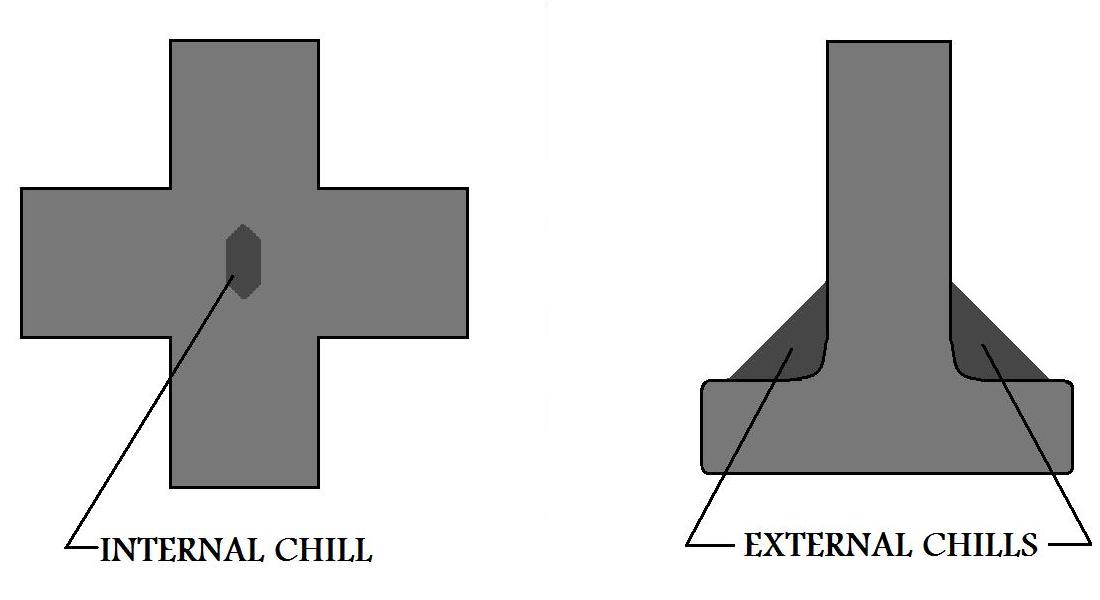
Chills are of two basic types. Internal chills are located inside the mold cavity and are
usually made of the same material as the casting. When the metal
solidifies the internal chills are fused into the metal casting itself. External chills are located just outside of the
casting. External chills are made of a material that can remove heat from the metal casting faster than the surrounding
mold material. Possible materials for external chills include iron, copper, and graphite. Figure 22 demonstrates
the use of the two types of chills to solve the hot spot problem in a + and T junction.
Figure:22
|
TOP
|
PRIVACY POLICY
|